2 gate control register (hscgt) – NEC PD17062 User Manual
Page 275
275
µ
PD17062
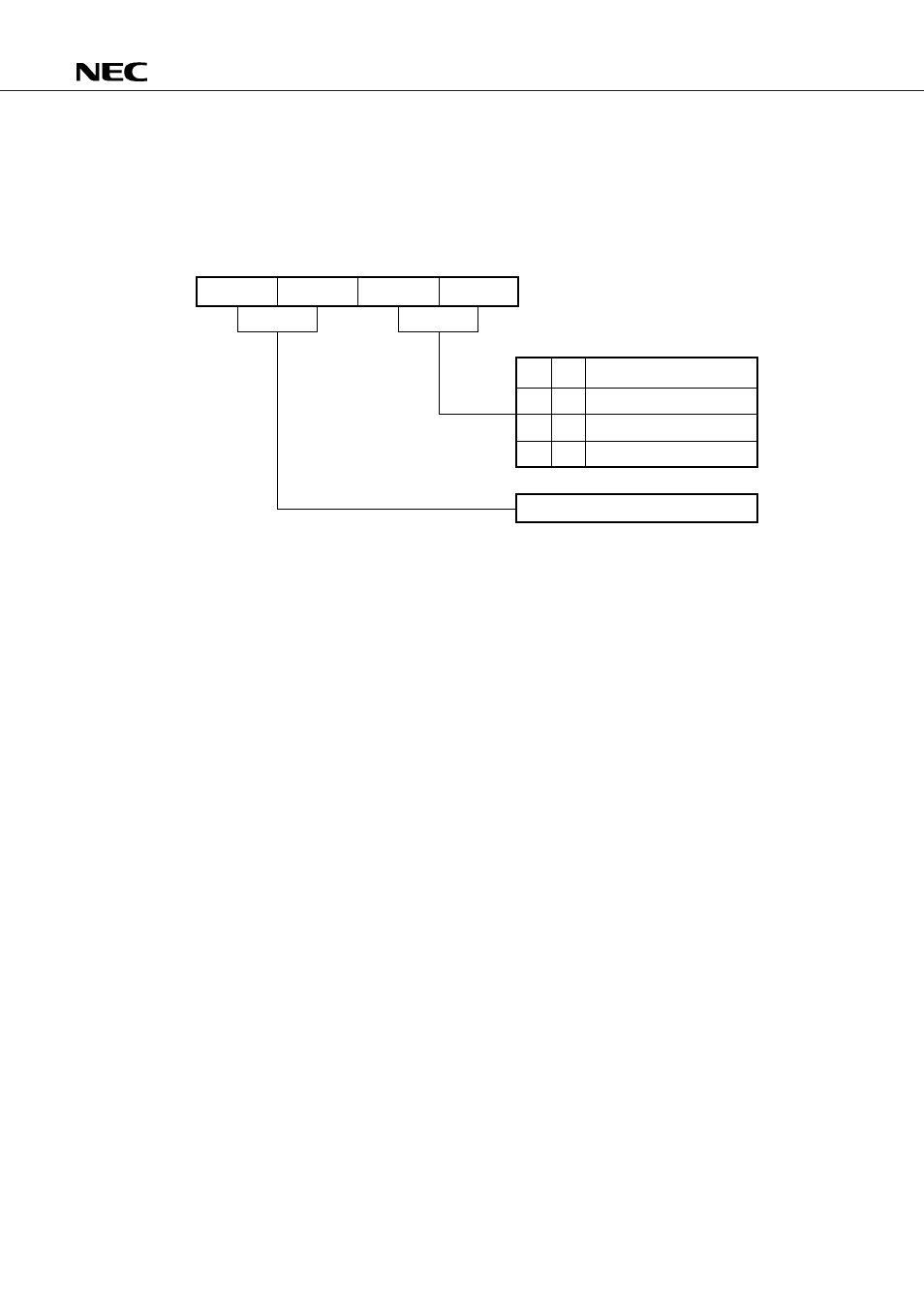
21.2 GATE CONTROL REGISTER (HSCGT)
The gate control register is a 2-bit register consisting of the HSCGT1 and HSCGT0 flags used to control the
gate. It is mapped in the register file at 11H. The gate control register can be read- and write-accessed through
the window register (system register) using the PEEK and POKE instructions, respectively.
The following modes can be set up using the gate control register.
Note The gate clock generator works only when this mode is selected.
21.2.1 Gate Closed Mode
In the gate closed mode, the gate is kept closed, disabling the HSC and gate clock generator from operating
(the content of the HSYNC counter does not change). This mode also turns off the bias input to the horizontal
sync signal counter, and therefore it should be selected when the port is used.
This mode is selected at a power-on reset and a clock stop.
21.2.2 Gate Open Mode
When the gate open mode is entered, the gate opens and causes the HSYNC counter to start counting the
input signal after it is reset.
When the HSYNC counter overflows, it goes back to 0.
In this mode, the input pin is biased.
21.2.3 1.69 ms gate mode
When the 1.69 ms gate mode is entered, the HSYNC counter is reset and starts counting the input signal
after 3.375/2 ms (with an error of 0 to 62.5
µ
s). The gate is kept open for 1.69 ms. The input pin is biased.
If the input signal is high when the gate is opened or closed, it is counted as one.
b
3
b
2
b
1
b
0
(RF11H)
HSCGT0
HSCGT1
HSCGT2
HSCGT3
0
0
1
0
1
0
1
1
Gate closed
Gate open
Open-gate time of 1.69 ms
Note
Not to be set
Fixed at 0