NEC PD17062 User Manual
Page 135
135
µ
PD17062
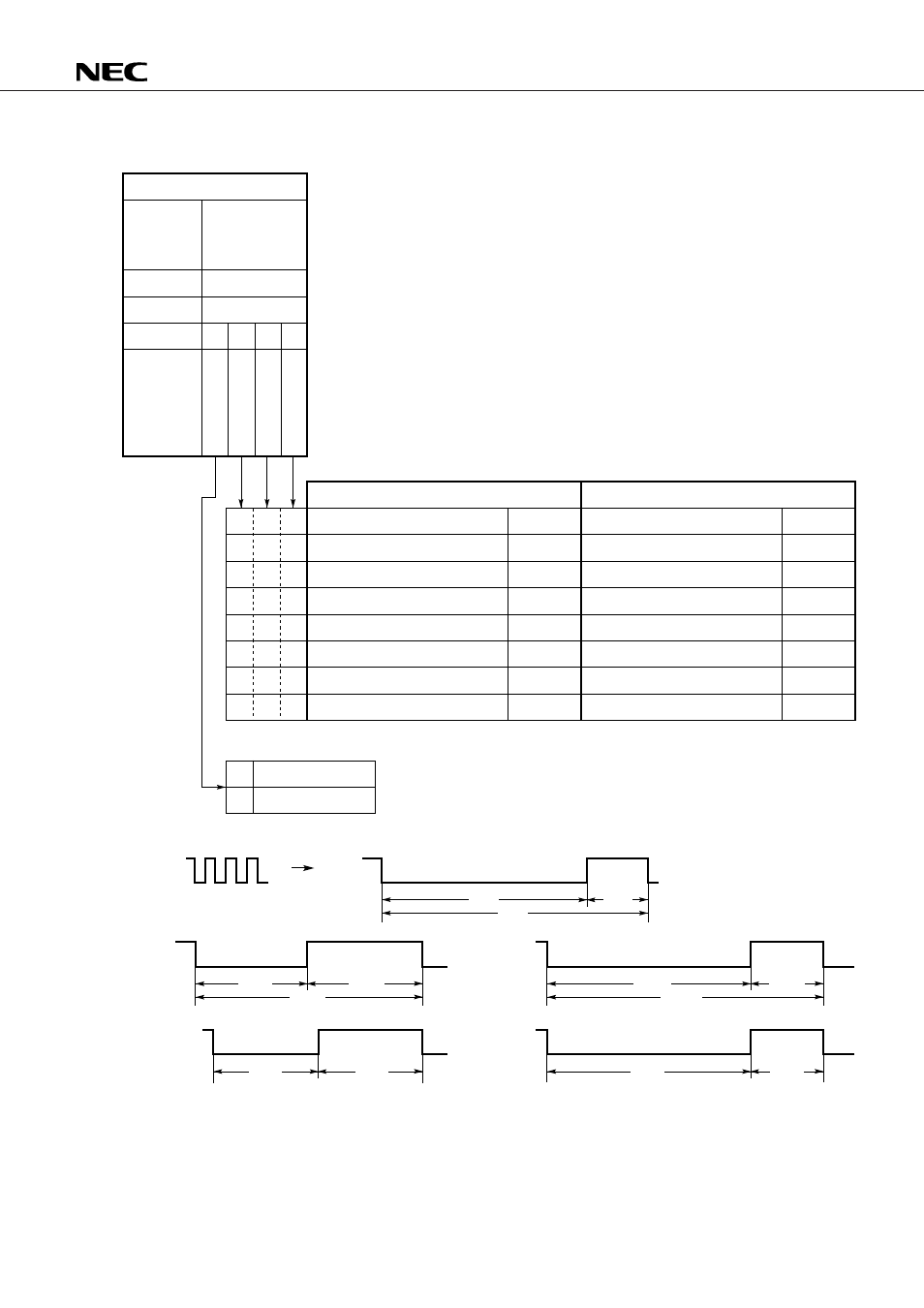
Fig. 12-2 Relationship Between the Timer Mode Select Register and Timer Interval Set Pulse
b
3
b
2
b
1
b
0
B
T
M
0
Z
X
B
T
M
0
C
K
2
B
T
M
0
C
K
1
B
T
M
0
C
K
0
09H
R/W
Read/Write
0
0
0
0
0
1
0
1
0
0
1
1
1
0
0
1
0
1
1
1
0
1
1
1
0
1
10 Hz ( 100 ms)
200 Hz ( 5 ms)
10 Hz ( 100 ms)
200 Hz ( 5 ms)
f
TMIN
/5 Hz (5/f
TMIN
s)
200 Hz ( 5 ms)
f
TMIN
/6 Hz (6/f
TMIN
s)
200 Hz ( 5 ms)
200 Hz ( 5 ms)
10 Hz ( 100 ms)
50 Hz ( 20 ms)
50 Hz ( 20 ms)
200 Hz ( 5 ms)
f
TMIN
/5 Hz (5/f
TMIN
s)
200 Hz ( 5 ms)
f
TMIN
/6 Hz (6/f
TMIN
s)
200 Hz
50 Hz
f
TMIN
/6 (Hz)
10 Hz
f
TMIN
/5 (Hz)
Control register
Register
Address
Bit
Flag symbol
Timer mode
select
(BTM0CK)
Selection of frequency (time) of the timer carry FF set pulse
Selection of frequency (time) of the timer interrupt pulse
Internal timer
Internal timer
Internal timer
Internal timer
External timer
Internal timer
External timer
Internal timer
Internal timer
Internal timer
Internal timer
Internal timer
Internal timer
External timer
Internal timer
External timer
f
TMIN
is the input frequency (50 or 60 Hz) at the P0B
2
/TMIN pin.
Disables the bias circuit.
Enables the bias circuit.
Duty cycle
Duty cycle
80 ms
1 ms
5 ms
4 ms
100 ms
20 ms
20%
80%
50%
10 ms
20 ms
10 ms
50%