General-purpose port – NEC PD17062 User Manual
Page 189
189
µ
PD17062
15. GENERAL-PURPOSE PORT
A general-purpose port outputs a high level, low level, or floating signal to an external circuit and reads
a high level or low level signal from an external circuit.
15.1 CONFIGURATION AND CLASSIFICATION OF GENERAL-PURPOSE PORT
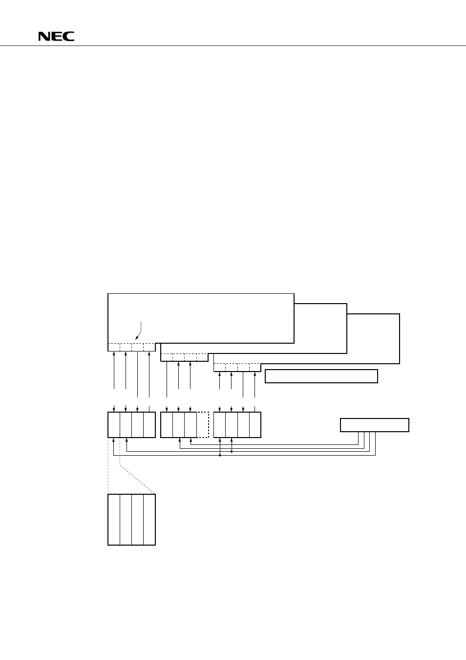
Fig. 15-1 shows a block diagram of the general-purpose port.
Table 15-1 lists the classifications of general-purpose ports.
As shown in Fig. 15-1, the general-purpose port consists of Port0A (P0A) to Port1C (P1C), that set data
according to addresses 70H to 73H (port register) in each bank of data memory. The same port register is
mapped to both BANK0 and BANK2.
Each port consists of general-purpose port pins. For example, Port0A consists of pin P0A
3
to pin P0A
0
.
As stated in Table 15-1, general-purpose ports are classified into I/O shared ports (I/O ports), input-only ports
(input ports), and output-only ports (output ports).
I/O ports are classified into bit I/O ports which allow I/O to be specified in 1-bit (1-pin) units and group
I/O ports in which I/O can be specified in 3-bit (3-pin) units .
Fig. 15-1 Block Diagram of General-Purpose Port
P
0
A
P
0
B
P
0
C
P
0
D
P
1
A
P
1
B
P
1
C
Fixed
at
0
P
0
A
P
0
B
P
0
C
P
0
D
P
0
A
pin
P
0
A
pin
P
0
A
pin
P
0
A
pin
BANK0
BANK1
BANK2
0
1
2
3
4
5
6
7
8
9
A
B
C
D
E
F
0
1
2
3
4
5
6
7
Column address
Row address
Data memory
Port register
System register
Bit
I/O
Bit
I/O
Bit
I/O
Group
I/O
Bit
I/O
Bit
I/O Out In
Out In
Out
I/O setting
Example configuration
of P0A pins
Control register
3
2
1
0