NEC PD17062 User Manual
Page 101
101
µ
PD17062
10.5.5 PWM Data Register
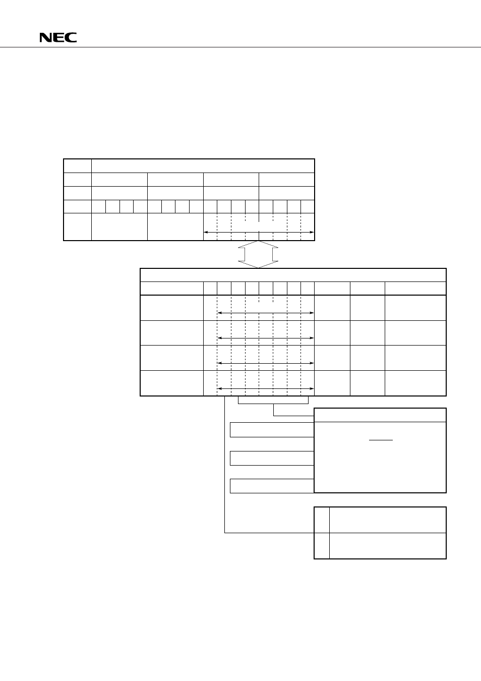
Fig. 10-8 shows how the PWM data register functions.
The PWM data register sets the duty cycle of the 6-bit D/A converter (PWM output) output.
The 6-bit D/A converter has four channels (pins PWM
3
, PWM
2
, PWM
1
, and PWM
0
). Because the duty cycle
can be set independently for each channel, four independent PWM duty cycle registers are also provided.
Fig. 10-8 PWM Data Register Functions
DBF3
0CH
DBF2
0DH
DBF1
0EH
DBF0
0FH
b
15
b
14
b
13
b
12
b
11
b
10
b
9
b
8
b
7
b
6
b
5
b
4
b
3
b
2
b
1
b
0
b
7
b
6
b
5
b
4
b
3
b
2
b
1
b
0
0
PWMR0
05H
Set the PWM output duty of each pin.
0
x
63
8
Use PWM pins as D/A converter.
Duty D =
x + 0.75
64
PWM
0
pin
PWM0
data register
PWMR1
06H
0
PWM
1
pin
PWM1
data register
PWMR2
07H
0
PWM
2
pin
PWM2
data register
PWMR3
08H
0
PWM
3
pin
PWM3
data register
(%)
0
0
Use PWM as 1-bit output pin.
Output contents of b
5
.
Symbol
Peripheral
address
Peripheral hardware
Name
Peripheral register
Name
Data buffer
Symbol
Address
Bit
Data
Don't care
Don't care
Transfer data
GET
PUT
Valid data
Frequency f = 15.625 kHz
(f: PWM output repetition frequency)