A/d converter, 1 principle of operation – NEC PD17062 User Manual
Page 233
233
µ
PD17062
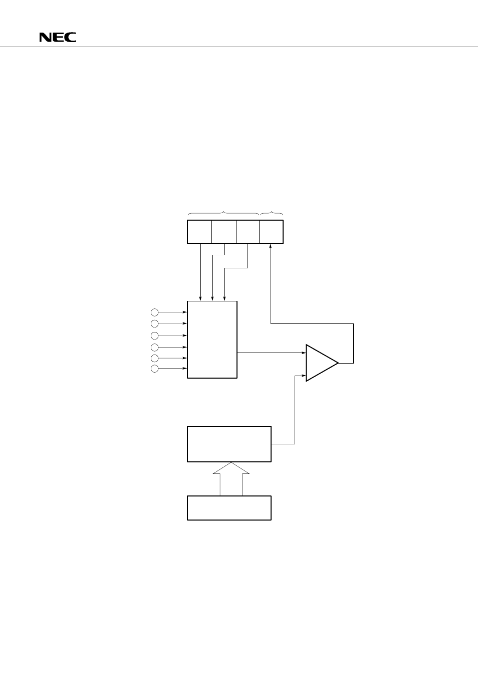
19. A/D CONVERTER
The
µ
PD17062 contains a 4-bit program-controlled A/D converter that operates with a successive compari-
son method.
19.1 PRINCIPLE OF OPERATION
The A/D converter in the
µ
PD17062 consists of a 4-bit resistor string-based D/A converter and comparator.
The D/A converter is set with data using a 4-bit register (ADCR) mapped at peripheral address 02H. The
result of comparison is judged according to the ADCCMP flag in the register file.
Fig. 19-1 A/D Converter Configuration
ADCCH
ADCCH ADCCH
AD
2
1
0
CCMP
ADCR
D/A converter
Channel
selector
RF : 21H
ADCCH (R/W)
ADCCMP (R)
Comparator
ADC0
ADC1
ADC2
ADC3
ADC4
ADC5
Peripheral address: 02H
ADCR (R/W)