NEC PD17062 User Manual
Page 225
225
µ
PD17062
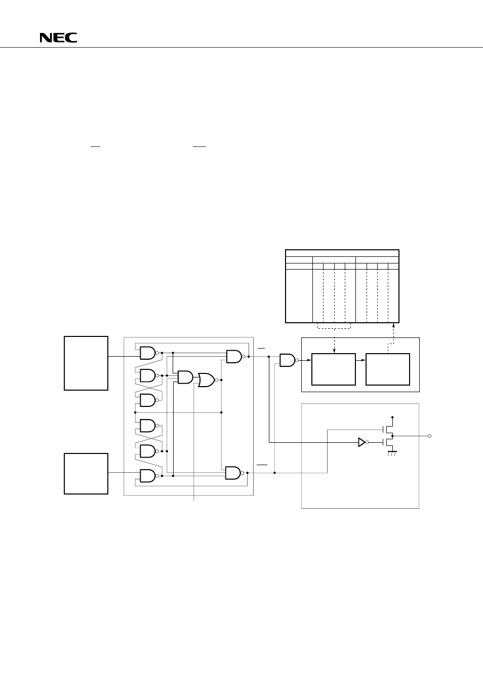
18.5 PHASE COMPARATOR (
φ
-DET), CHARGE PUMP, AND UNLOCK DETECTION BLOCK
18.5.1 Configuration of the Phase Comparator (
φ
-DET), Charge Pump, and Unlock Detection Block
Fig. 18-5 shows the configuration of the phase comparator (
φ
-DET), charge pump, and unlock detection
block.
The phase comparator compares the phase of the output frequency “f
N
” of the programmable divider (PD)
with the reference frequency output “f
r
” of the reference frequency generator, and outputs the up request
signal (UP) or down request signal (DW).
The charge pump directs the output of the phase comparator to the error output pin (EO pin).
The unlock detection block consists of a delay control circuit and unlock flip-flop (FF). It detects the unlock
state of the PLL frequency synthesizer.
Sections 18.5.2, 18.5.3, and 18.5.4 explain the operation of the phase comparator, charge pump, and unlock
detection block, respectively.
Fig. 18-5 Configuration of the Phase Comparator, Charge Pump, and Unlock Detection Block
32H
22H
b
3
b
2
b
1
b
0
b
3
b
2
b
1
b
0
P
L
U
L
S
E
N
3
P
L
U
L
S
E
N
2
P
L
U
L
S
E
N
1
P
L
U
L
S
E
N
0
0
0
0
P
L
L
U
L
Control register
EO
V
DD
P-ch
N-ch
UP
DW
f
r
f
N
Address
Bit
Flag
symbol
Unlock detection block
Delay control
Unlock FF
Charge pump
Reference
frequency
generator
Programmable
divider
PLL disable signal
Phase comparator ( -DET)
φ