NEC PD17062 User Manual
Page 218
218
µ
PD17062
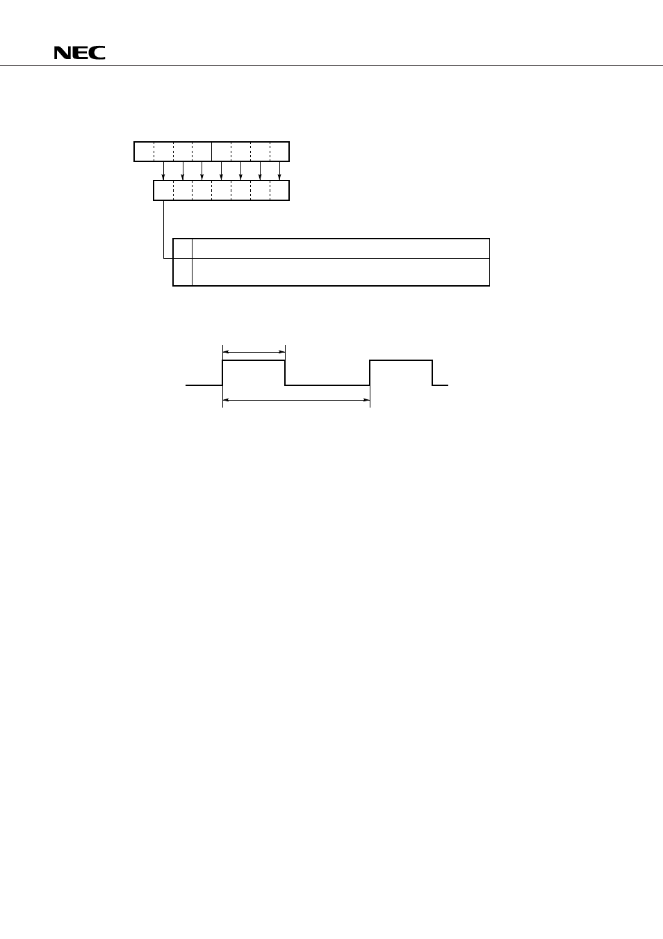
Fig. 17-1 PWMR Structure and the Corresponding DBF Bits
Fig. 17-2 Waveform Output from the PWM Pin
b
3
b
2
b
1
b
0
b
3
b
2
b
1
b
0
b
6
b
5
b
4
b
3
b
2
b
1
b
0
0
1
PWMR
DBF1 (0EH)
DBF0 (0FH)
The PWM pin is used as a D/A converter.
The PWM pin is used as a one-bit output port (through mode), which
outputs the content of b
5
.
t
64
s
t = n + 0.75 (
s) (where n is a value specified in the PWMR)
µ
µ