3 general-purpose i/o ports (p0a, p0b, p1b, p1c) – NEC PD17062 User Manual
Page 194
194
µ
PD17062
15.3 GENERAL-PURPOSE I/O PORTS (P0A, P0B, P1B, P1C)
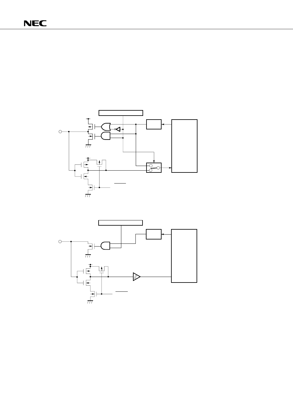
15.3.1 Configuration of I/O Ports
In the following, (1) to (3) explain the configuration of the I/O ports.
(1) P0A (P0A
3
, P0A
2
pins)
P0B (P0B
3
, P0B
2
, P0B
1
, P0B
0
pins)
P1B (P1B
3
, P1B
2
, P1B
1
, P1B
0
pins)
P1C (P1C
3
, P1C
2
, P1C
1
pins)
(2) P0A (P0A
1
, P0A
0
pins)
15.3.2 How to Use I/O Ports
An I/O port is set as an input or output port according to the contents of each I/O selection register of P0A,
P0B, P1B, and P1C of the control register.
I/O of the bit I/O port (P0A, P0B, P1B) can be set in 1-bit (1-pin) units. I/O of the group I/O port (P0C) can
be set in 3-bit (3-pin) units.
Output data is set and input data is read when a data write instruction or data read instruction is executed
in the corresponding port register.
Section 15.3.3 describes the I/O selection register of each port.
Sections 15.3.4 and 15.3.5 explain the use of an input port and output port.
V
DD
V
DD
OR
AND
1
0
I/O switching flag
Output
latch
Write
instruction
Port register
(1 bit)
Read
instruction
RESET (except P1C)
Read instruction (P1C only)
V
DD
AND
RESET
I/O switching flag
Output
latch
Write
instruction
Port register
(1 bit)
Read
instruction