NEC PD17062 User Manual
Page 224
224
µ
PD17062
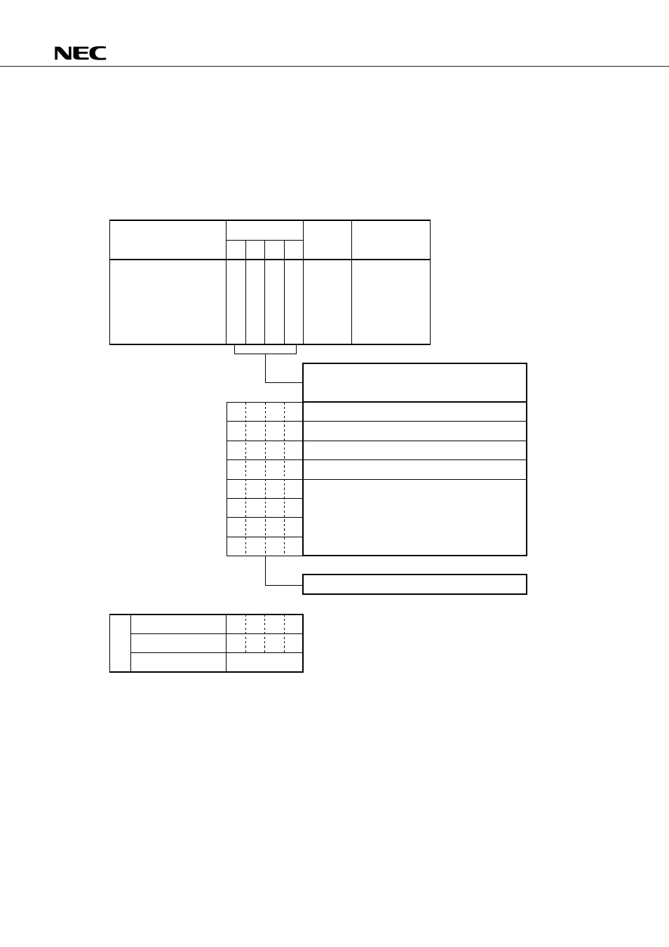
18.4.2 PLL Reference Mode Select Register Configuration and Functions
Fig. 18-4 shows the configuration and functions of the PLL reference mode select register.
When the PLL reference mode select register selects the PLL disable mode, the VCO pin is pulled down
internally, and the EO pin floats.
See Section 18.6 for the PLL disable mode.
Fig. 18-4 PLL Reference Mode Select Register Configuration and Functions
b
3
b
2
b
1
b
0
P
L
L
R
F
C
K
3
P
L
L
R
F
C
K
2
P
L
L
R
F
C
K
1
P
L
L
R
F
C
K
0
13H
Read/write
R/W except
PLLRFCK1, which
is read-only
0
0
1
0
0
0
1
1
0
1
1
0
1
1
1
1
0
1
1
1
1
0
1
0
1
0
1
1
1
1
1
0
6.25 kHz
12.5 kHz
25 kHz
1
1
1
1
1
1
1
1
CE
Register
Address
Flag symbol
PLL reference mode
select (PLRFMODE)
Specify the reference frequency f
r
for the PLL
frequency synthesizer.
PLL disable
Not to be set
Fixed at 1
Upon reset
Clock stop
Power-on
Kept unchanged