NEC PD17062 User Manual
Page 170
170
µ
PD17062
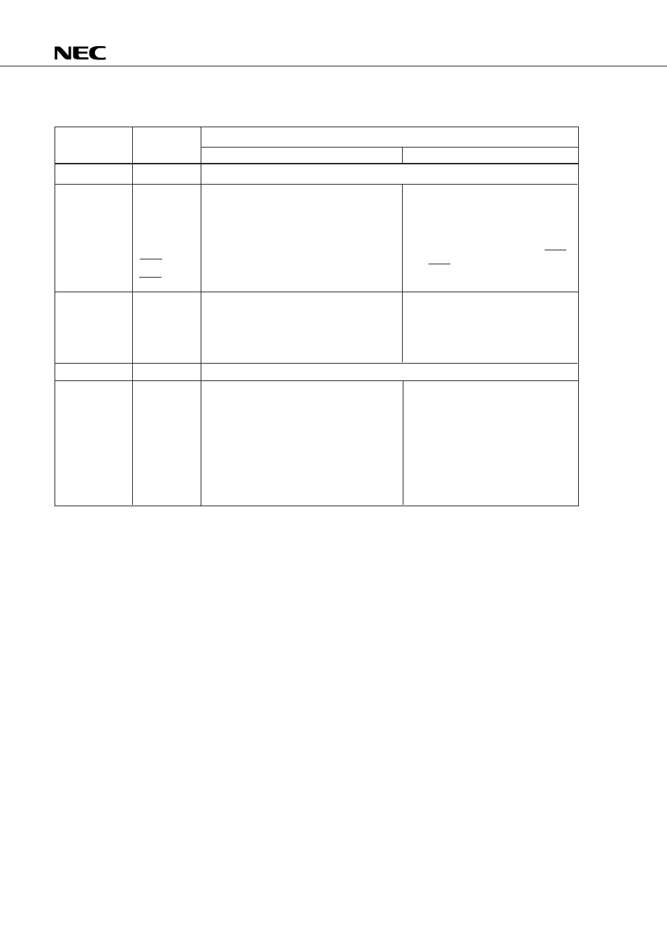
Table 13-2 State of Each Pin During the Halt or Clock Stop State and Cautions to Be Taken (2/2)
INT
NC
RED
GREEN
BLUE
BLANK
H
SYNC
V
SYNC
PWM
3
PWM
2
PWM
1
PWM
0
ADC
0
X
IN
X
OUT
Clock stop state
State of each pin and cautions in processing
Halt state
Pin symbol
Pin function
If the pin is floating, external noise causes the current drain to increase.
The output pins remain in the state in
which they were when the HALT
instruction was executed. If the IDCEN
flag is set, the current drain increases.
It is necessary to take the same cautions
as for the general-purpose output port.
The pin becomes floating.
The current drain varies with the
waveform of the oscillation output of the
clock oscillator.
The larger the amplitude, the current drain
becomes lower.
The oscillation amplitude of the oscillator
varies depending on its crystal and load
capacitance; evaluation is required.
The IDC is disabled.
Each pin behaves as follows:
The current drain will not increase,
even if the RED, GREEN, and BLUE
pins output a low level, or the H
SYNC
and V
SYNC
pins are floating.
All pins output a low level.
The X
IN
pin is internally pulled
down, and the X
OUT
pin outputs a
high level.
Interrupt
IDC
D/A converter
A/D converter
Clock oscillator