Timer, 1 timer configuration – NEC PD17062 User Manual
Page 133
133
µ
PD17062
12. TIMER
The timer functions are used to manage the time in creating programs.
12.1 TIMER CONFIGURATION
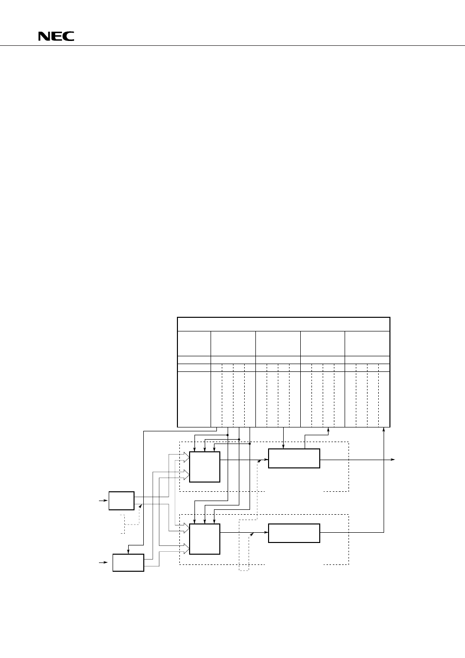
Fig. 12-1 shows the configuration of the timer.
The timer consists of two blocks, timer carry flip-flop (timer carry FF) block and timer interrupt block, as
shown in Fig. 12-1.
The clock generation circuit, which specifies time intervals for the timer carry FF and timer interrupts,
consists of an 8 MHz frequency divider, selector A, selector B, bias circuit, and a timer mode select register
(BTM0CK at address 09H), which is a control register.
12.1.1 Timer Carry FF Block Configuration
The timer carry FF block consists of selector A, timer carry FF, a timer carry FF judge register (BTM0CYJDG
at address 17H), which is a control register, as shown in Fig. 12-1.
12.1.2 Timer Interrupt Block Configuration
The timer interrupt block consists of selector B, an interrupt control block, an interrupt permission register
(INTPM at address 2FH), which is a control register, and an interrupt request register (INTREQ at address 3FH),
as shown in Fig. 12-1.
Fig. 12-1 Timer Configuration
09H
2FH
3FH
17H
b
3
b
2
b
1
b
0
b
3
b
2
b
1
b
0
b
3
b
2
b
1
b
0
b
3
b
2
b
1
b
0
B
T
M
0
Z
X
B
T
M
0
C
K
2
B
T
M
0
C
K
1
B
T
M
0
C
K
0
I
P
S
I
O
0
I
P
V
S
Y
N
I
P
B
T
M
0
I
P
N
C
I
R
Q
S
I
O
0
I
R
Q
V
S
Y
N
I
R
Q
B
T
M
0
I
R
Q
N
C
0
0
0
B
T
M
0
C
Y
10 Hz
50 Hz
200 Hz
8 MHz
50/60 Hz
100 ms (10 Hz), 20 ms (50 Hz), or 5 ms (200 Hz) can be selected.
Control register
Register
Address
Bit
Flag symbol
Timer mode
select
(BTM0CK)
Interrupt
permission
(INTPM)
Interrupt
request
(INTREQ)
Timer carry
FF judge
(BTM0CYJDG)
Selector
B
Interrupt
control block
Interrupt
request
signal
Frequency
divider
Timer interrupt block
Selector
A
Timer carry FF
Bias
Timer carry FF block