NEC PD17062 User Manual
Page 157
157
µ
PD17062
13.4.2 Halt Release Conditions
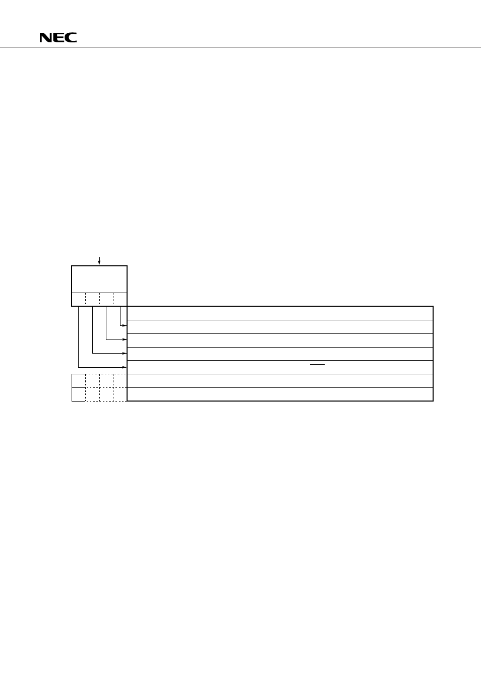
Fig. 13-3 summarizes the release conditions.
As shown in Fig. 13-3, the halt release condition is 4-bit data specified in the operand h of the HALT h
instruction.
The halt state is released when a condition specified as 1 in the operand h is satisfied.
Upon release of the halt state, the subsequent instructions after the HALT h instruction are executed
sequentially.
If multiple release conditions are specified at a time, the halt state is released when only one of them is
satisfied.
Also when a power-on or CE reset occurs, the halt state is released and the device is reset.
If the operand h is 0000B, no halt release condition is specified.
Under this condition, the halt state is released by resetting (power-on or CE reset) the device.
Sections 13.4.3 to 13.4.6 explain the timer carry FF, interrupt, and key entry as halt release conditions.
Fig. 13-3 Halt Release Conditions
b
3
b
2
b
1
b
0
0
1
HALT h (4 bits)
Operand bits
Specify a condition to release the halt state.
The halt state is released by a high level applied to a key entry pin (P0D
3
/ADC
5
to P0D
0
/ADC
2
pins).
The halt state is released when the timer carry FF is set to 1.
Undefined (to be fixed at 0)
The halt state is released when an interrupt (INT
NC
pin, timer, V
SYNC
, serial interface) is accepted.
The halt state is not released even when the condition is satisfied.
The halt state is released when the condition is satisfied.