2 d/a converter configuration – NEC PD17062 User Manual
Page 234
234
µ
PD17062
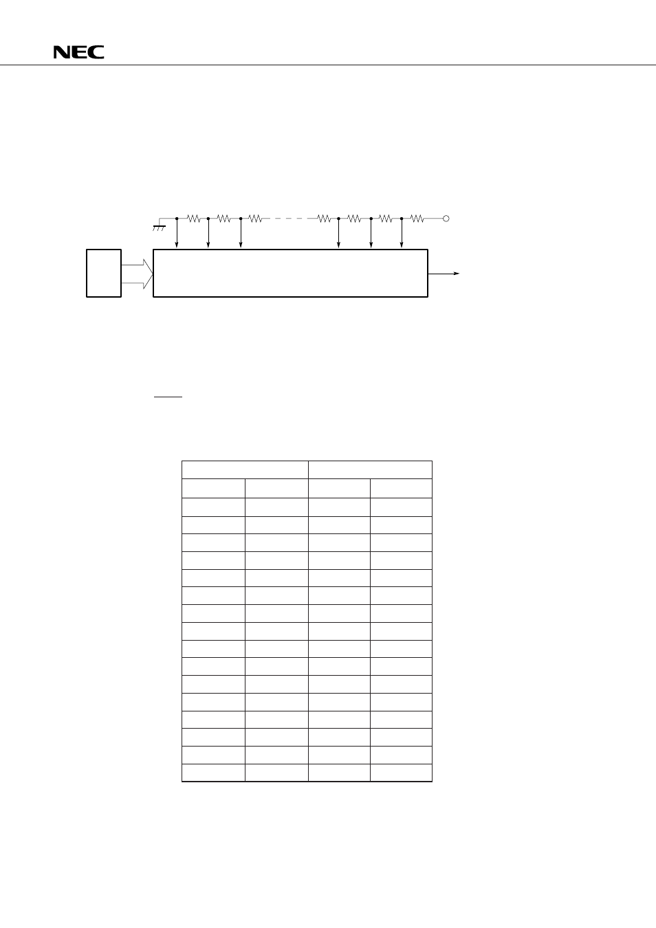
19.2 D/A CONVERTER CONFIGURATION
The D/A converter used in the A/D converter of the
µ
PD17062 is a resistor string D/A converter consisting
of 16 resistors connected in series between the V
DD
and GND pins in which a voltage at each resistor connection
point is selected. The configuration of the D/A converter is shown in Fig. 19-2.
Fig. 19-2 D/A Converter Configuration
With the configuration shown above, the D/A converter outputs a ground level when the ADCR is set with
value 0000B. It also outputs 1/32
×
V
DD
when the ADCR is set with 0001B. The following expression represents
the reference voltage V
REF
that the D/A converter outputs when the ADCR is set with value n (decimal).
V
REF
= V
DD
×
2n – 1
(where 15
≥
n
≥
1)
32
Table 19-1 D/A Converter Reference Voltage
ADCR
4
0
1
2
13
14
15
Selector
1/2R
R
R
R
R
R
3/2R
V
DD
D/A output
(reference voltage)
Set data (ADCR)
Reference voltage (V
REF
)
Hexadecimal
Binary
×
V
DD
V
DD
= 5 V
0
0000
0
0 [V]
1
0001
1/32
0.15625
2
0010
3/32
0.46875
3
0011
5/32
0.78125
4
0100
7/32
1.09375
5
0101
9/32
1.40625
6
0110
11/32
1.71875
7
0111
13/32
2.03125
8
1000
15/32
2.34375
9
1001
17/32
2.65625
A
1010
19/32
2.96875
B
1011
21/32
3.28125
C
1100
23/32
3.59375
D
1101
25/32
3.90625
E
1110
27/32
4.21875
F
1111
29/32
4.53125