4 ser – Yaskawa SGDS Sigma III Servo Amplifier User Manual
Page 69
3 SERVOPACK Specifications and Dimensional Drawings
3.3.5 Three-phase 200 V, 3.0~5.0kW
3-12
3.4 SERVOPACK Power Supply Capacities and Power Losses
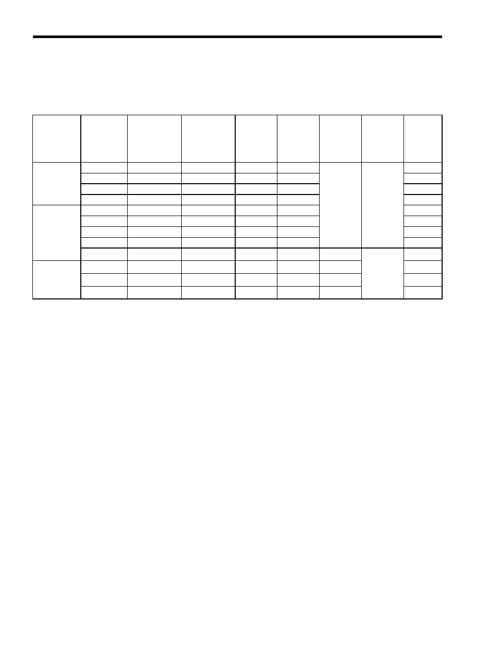
The following table shows SERVOPACK power supply capacities and power losses at the rated output.
* 1. SERVOPACKs with a capacity of 50 to 400 W do not have built-in regenerative resistors. If the
regenerative energy exceeds the specified value, connect an external regenerative resistor. Refer to
11.1.3 Calculating the Required Capacity of Regenerative Resistors.
* 2. Regenerative resistor power losses are allowable losses. Take the following action if this value is
exceeded.
• Remove the lead from the internal regenerative resistor in the SERVOPACK.
• Install an external regenerative resistor.
Note: External regenerative resistors are optional. Refer to 5.7 Connecting Regenerative Resistors and
4.4.3 External Regenerative Resistor for details.
Table 3.1 SERVOPACK Power Losses at Rated Output
Main Circuit
Power
Supply
Maximum
Applicable
Servomotor
Capacity
kW
SERVOPACK
Model
SGDS-
Power Supply
Capacity
kW
Output
Current
(Effective
Value)
A
Main Cir-
cuit Power
Loss
W
Regenera-
tive Resis-
tor Power
Loss
W
Control
Circuit
Power
Loss
W
Total
Power
Loss
W
Single-
phase 100 V
0.05
A5F
0.25
0.66
5.2
−
∗1
13
18.2
0.10
01F
0.40
0.91
12
25
0.20
02F
0.60
2.1
16.4
29.4
0.40
04F
1.2
2.8
24
37
Single-
phase 200 V
0.05
A5A
0.25
0.66
4.6
17.6
0.10
01A
0.40
0.91
6.7
19.7
0.20
02A
0.75
2.1
13.3
26.3
0.40
04A
1.2
2.8
20
33
0.75
08A
2.2
5.5
47
12
*2
15
74
Three-phase
200 V
1.0
10A
2.3
7.6
55
12
*2
82
2.0
20A
4.3
11.6
92
14
*2
121
3.0
30A
5.9
18.5
120
28
*2
163