4 related parameters, 1) parameters, 4 related parameters -9 – Yaskawa SGDS Sigma III Servo Amplifier User Manual
Page 288
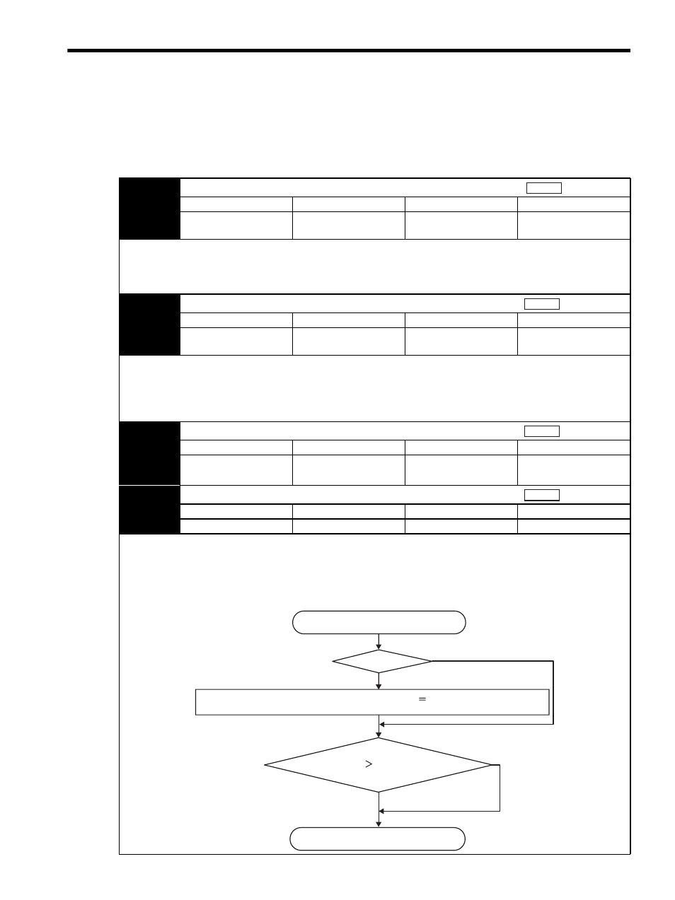
9.4 Related Parameters
9-9
9.4 Related Parameters
(1) Parameters
The following table shows the parameters related to the fully-closed control of the SGDS-
12A
SERVOPACKs.
Pn20A
Number of External Scale Pitches
Setting Range
Setting Unit
Factory Setting
Setting Validation
100 to 1048576
pitch/Rev
1 pitch/Rev
32768 P/Rev
After restart
Sets the number of pitches (cycles) of the sine wave for the external scale.
Set the number of pitches between 100 to 1048576 (2
20
) pulses. Any fractions cause differences on the speed monitor
signals of the position loop gain (Pn102) and feed forward (Pn109), but do not cause position errors. Set the parameter to
the number of pulses multiplied by 1.
Pn281
Encoder Output Resolution
Setting Range
Setting Unit
Factory Setting
Setting Validation
1 to 256
/ (pitch
× 4 multiplier)
1P/
(pitch
× 4 multiplier)
20P/
(pitch
× 4 multiplier)
After restart
Sets the number of output pulses of the PG output signal (PAO, PBO and PCO) from the SERVOPACK to an external
device.
The position data from the external scale is divided by the number of pulses set in Pn281 and then output. Set the number
of output pulses per pitch multiplied by 4.
If using a fully-closed encoder for the reversed rotation mode, the signal PBO is reversed and output.
Pn51B
Excessive Error Level Between Servomotor and Load Position
Setting Range
Setting Unit
Factory Setting
Setting Validation
0 to 1073741824(2
30
)
reference units
1 reference unit
1000 reference units
Immediately
Pn52A
Multiplier per One Fully-Closed Rotation
Setting Range
Setting Unit
Factory Setting
Setting Validation
1 % to 100%
1%
20%
Immediately
If the detected difference between the external scale position and the encoder position is above the set level, the alarm
A.D10 “Excessive error between servomotor and load positions” occurs. This function can be used to prevent runaway due
to a damaged scale and to detect slip in the belt mechanism.
The alarm A.D10 “Excessive error between servomotor and load positions” is detected as shown in the following
flowchart.
position
position
position
position
Detection for "Excessive Error Between
Servomotor and Load Positions" starts.
Error Between Servomotor
and Load Positions Pn51B "Excessive Error
Level Between Servomotor
and Load Positions"
Error Between Servomotor and Load Positions
Difference between
servomotor and load positions × {100% −
( Pn52A "Multiplier per 1 fully-closed rotation" [%])}
Servomotor
1 rotation
No
No
Yes
Yes
Detection for "Excessive Error Between
Servomotor and Load Positions" ends.