4 wiring mechatrolink ii communications, 1 wiring example mechatrolink ii communications, 4 wiring mecha – Yaskawa SGDS Sigma III Servo Amplifier User Manual
Page 116: 1 wirin, 4 wiring mechatrolink ii communications -13
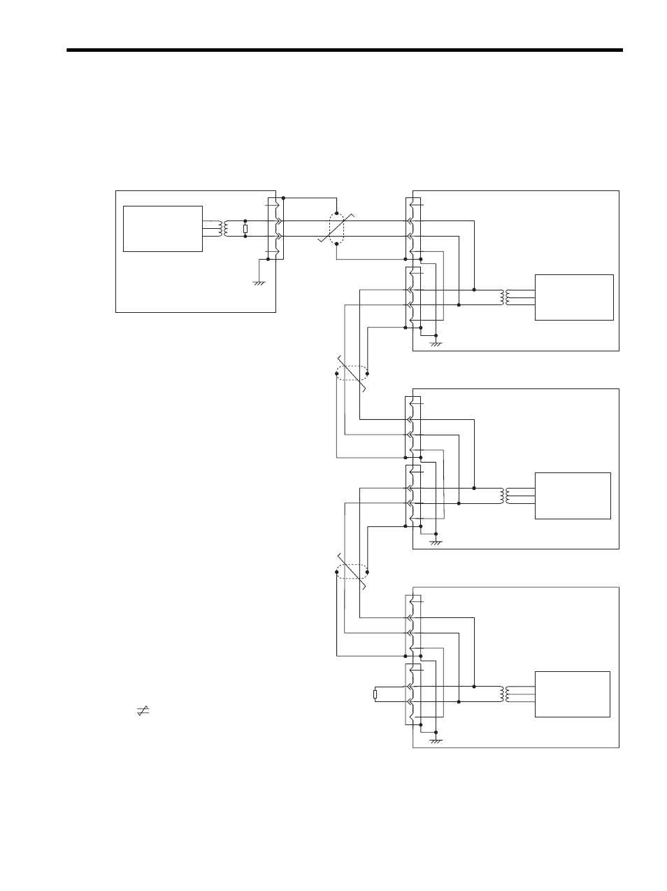
5.4 Wiring MECHATROLINK II Communications
5-13
5.4 Wiring MECHATROLINK II Communications
The following diagram shows an example of connections between a host controller and a SERVOPACK using
MECHATROLINK II communications cables (CN6A, CN6B).
5.4.1 Wiring Example MECHATROLINK II Communications
SERVOPACK (first station)
Pulse transformer
SERVOPACK (first station)
Pulse transformer
SERVOPACK (first station)
Pulse transformer
Host controller
Pulse transformer
Terminating Multiple Axis Connections
*
represents twisted pair wires.
Always connect a Terminator (JEPMC-W6020: 120
Ω) between
pins 2 and 3 of the end connector of the last SERVOPACK. Also
connect a terminating resister 120
Ω) and the shield at the host
controller.
MECHATROLINK-II
I/F
1
2
3
4
CN6A
CN6B
1
2
3
4
/S
S
SH
/S
S
SH
FG
1
2
3
4
CN6A
CN6B
1
2
3
4
/S
S
SH
/S
S
SH
FG
1
2
3
4
CN6A
CN6B
1
2
3
4
/S
S
SH
/S
S
SH
FG
1
2
3
4
/S
S
SH
120
Ω
FG
120
Ω
MECHATROLINK-II
I/F
MECHATROLINK-II
I/F
MECHATROLINK-II
I/F
- Tag Generator (30 pages)
- MP3300iec (82 pages)
- 1000 Hz High Frequency (18 pages)
- 1000 Series (7 pages)
- PS-A10LB (39 pages)
- iQpump Micro User Manual (300 pages)
- 1000 Series Drive Option - Digital Input (30 pages)
- 1000 Series Drive Option - CANopen (39 pages)
- 1000 Series Drive Option - Analog Monitor (27 pages)
- 1000 Series Drive Option - CANopen Technical Manual (37 pages)
- 1000 Series Drive Option - CC-Link (38 pages)
- 1000 Series Drive Option - CC-Link Technical Manual (36 pages)
- 1000 Series Drive Option - DeviceNet (37 pages)
- 1000 Series Drive Option - DeviceNet Technical Manual (81 pages)
- 1000 Series Drive Option - MECHATROLINK-II (32 pages)
- 1000 Series Drive Option - Digital Output (31 pages)
- 1000 Series Drive Option - MECHATROLINK-II Technical Manual (41 pages)
- 1000 Series Drive Option - Profibus-DP (35 pages)
- AC Drive 1000-Series Option PG-RT3 Motor (36 pages)
- Z1000U HVAC MATRIX Drive Quick Start (378 pages)
- 1000 Series Operator Mounting Kit NEMA Type 4X (20 pages)
- 1000 Series Drive Option - Profibus-DP Technical Manual (44 pages)
- CopyUnitManager (38 pages)
- 1000 Series Option - JVOP-182 Remote LED (58 pages)
- 1000 Series Option - PG-X3 Line Driver (31 pages)
- SI-EN3 Technical Manual (68 pages)
- JVOP-181 USB Copy Unit (2 pages)
- JVOP-181 (22 pages)
- SI-EN3 (54 pages)
- MECHATROLINK-III (35 pages)
- SI-ET3 (49 pages)
- EtherNet/IP (50 pages)
- SI-EM3 (51 pages)
- 1000-Series Option PG-E3 Motor Encoder Feedback (33 pages)
- 1000-Series Option SI-EP3 PROFINET (56 pages)
- PROFINET (62 pages)
- AC Drive 1000-Series Option PG-RT3 Motor (45 pages)
- SI-EP3 PROFINET Technical Manual (53 pages)
- A1000 Drive Option - BACnet MS/TP (48 pages)
- 120 Series I/O Modules (308 pages)
- A1000 12-Pulse (92 pages)
- A1000 Drive Software Technical Manual (16 pages)
- A1000 Quick Start (2 pages)
- JUNMA Series AC SERVOMOTOR (1 page)
- A1000 Option DI-101 120 Vac Digital Input Option (24 pages)