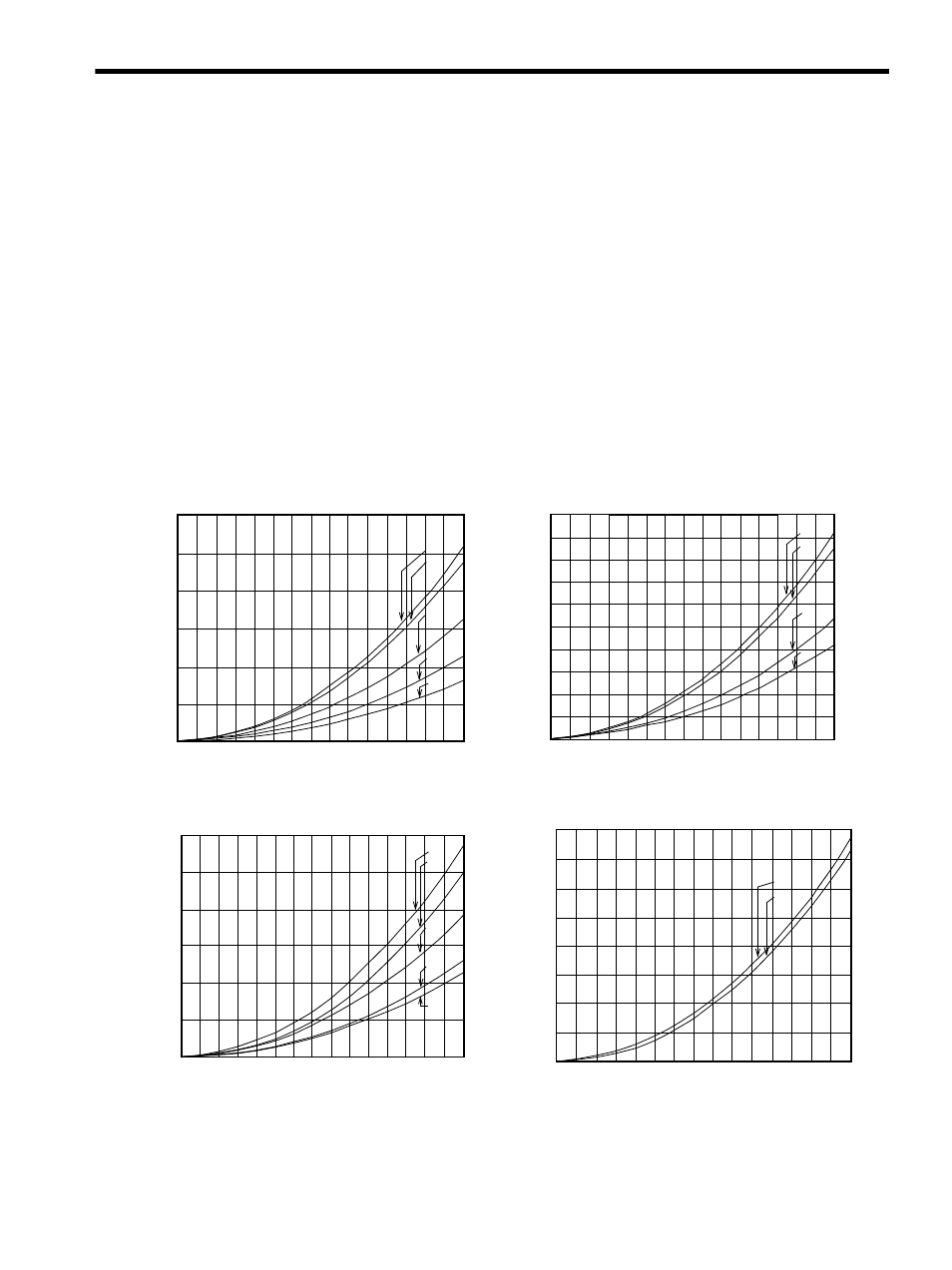
B) servomotor winding resistance loss – Yaskawa SGDS Sigma III Servo Amplifier User Manual
Page 324

11.1 Servomotor Capacity Selection Examples
11-9
If the energy consumed by load loss (in step 2 above) is unknown, then perform the calculation using E
L
= 0.
When the operation period in regeneration mode is continuous, add the following items to the above
calculation procedure in order to find the required capacity (W) for the regenerative resistor.
• Energy for continuous regeneration mode operation period: E
G
(joules)
• Energy consumed by regenerative resistor: E
K
= E
S
- (E
L
+ E
M
+ E
C
) + E
G
• Required capacity of regenerative resistor: W
K
= E
K
/ (0.2
× T)
Here, E
G
= (2
π
/60) N
MG
T
G
t
G
• T
G
: Servomotor’s generated torque (N·m) in continuous regeneration mode operation period
• N
MG
:Servomotor rotation speed (RPM) for same operation period as above
• t
G
:Same operation period (s) as above
(b) Servomotor Winding Resistance Loss
The following diagrams show the relationship, for each servomotor, between the servomotor’s generated
torque and the winding resistance loss.
• SGMAH Servomotor, 200V
• SGMAH Servomotor, 100V
• SGMPH Servomotor, 200V
• SGMPH Servomotor, 100V
200
250
150
100
50
0
0
100
200
300
300
Torque (%)
(W)
SGMAH-
04A
08A
01A, 02A
A5A
A3A
Loss
200
180
160
140
120
100
80
60
40
20
0
0
100
200
300
Torque (%)
SGMAH-
01B
02B
A5B
A3B
(W)
Lo
ss
200
250
150
100
50
0
0
100
200
300
300
Torque (%)
(W)
SGMPH-
15A
08A
04A
01A
02A
Loss
160
140
120
100
80
60
40
20
0
0
100
200
300
Torque (%)
(W)
SGMPH-
02B
01B
Loss
