2 list of parameters, E. refer to 11.2.2 list of parameters, 2 list of parameters -12 – Yaskawa SGDS Sigma III Servo Amplifier User Manual
Page 327

11 Appendix
11.2.2 List of Parameters
11-12
11.2.2 List of Parameters
Use the following table for recording parameters. Parameter changing method is as follows:
: Can be changed at any time, and immediately validated after changing. (Called an online parameter.)
: Can be changed when DEN=1. Immediately validated after changing. Do not change when DEN = 0. Doing
so may lead to overrun (Called an offline parameter.)
∆: Validated after a Set Up Device command is sent, when loading and using parameters at power ON. Also
validated when turning OFF and then ON the power supply again after a Write Non-volatile Parameter
(PPRM_WR) command is sent.
Parameter
No.
Name
Data
Size
Setting Range
Units
Factory
Setting
Changing
Method
Reference
Section
Pn000
Function Selection Basic Switch 0
2
−
−
0000
∆
Pn001
Function Selection Application Switch
1
2
−
−
0000
∆
−
Note:
∆: Validated after a Set Up Device command is sent, when loading and using parameters at
power ON. Also validated when turning OFF and then ON the power supply again after a
Write Non-volatile Parameter (PPRM_WR) command is sent.
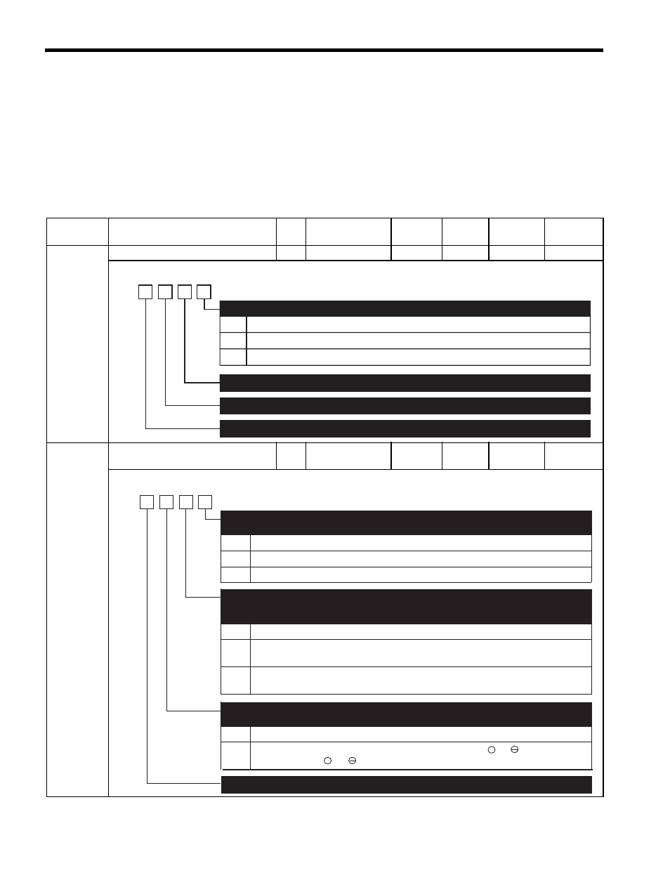
0
1
2 and 3
Sets CCW as forward direction.
Sets CW as forward direction (Reverse Rotation Mode).
Reserved (Do not change)
Rotation Direction Selection
Reserved (Do not change)
Reserved (Do not change)
Reserved (Do not change)
4th
digit
3rd
digit
2nd
digit
1st
digit
n.
0
1
2
0
1
2
Stops the motor by applying dynamic brake (DB).
Stops the motor by applying dynamic brake (DB) and then releases DB.
Makes the motor coast to a stop state without using the dynamic brake (DB).
Stops the motor by applying DB or by coasting.
Sets the torque of Pn406 to the maximum value, decelerate the motor to a stop, and then sets it
to servolock state.
Sets the torque of Pn406 to the maximum value, decelerates the motor to a stop, and then sets it
to coasting state.
Servo OFF or Alarm Stop Mode
(Refer to "7.6.1 Using the Dynamic Brake.")
Overtravel (OT) Stop Mode
(Refer to "6.7.4 Operation Sequence When OT (Overtravel Limit Switch) Signal Is Input,
"7.3.2 Setting the Overtravel Limit Function.")
0
1
Not applicable to DC power input: Input AC power supply through L1, L2 (, and L3) terminals.
AC/DC Power Input Selection
(Refer to "5.1.3 Typical Main Circuit Wiring Examples.")
Reserved (Do not change)
4th
digit
3rd
digit
2nd
digit
1st
digit
n.
Applicable to DC power input: Input DC power supply between B1/ + and , or input DC power
supply between B1/ + and 1.
an interlock state.
