27 in – Yaskawa SGDS Sigma III Servo Amplifier User Manual
Page 164
6.3 Main Commands
6-33
6.3.27 Interpolation Feeding with Position Detection (LATCH: 38H)
• Related Parameters
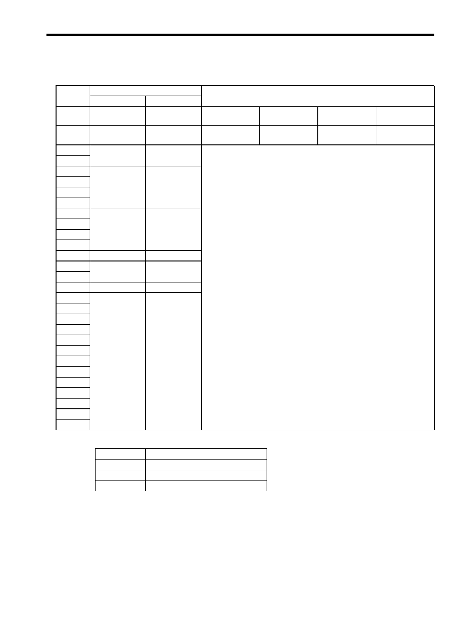
Byte
LATCH
Description
Command
Response
1
38H
38H
Processing
classifications
Motion command
group
Synchronization
classifications
Synchronous
2
LT_SGN
ALARM
Processing time
Within communi-
cations cycle
Subcommand
Can be used
3
OPTION
STATUS
• Performs interpolation feeding and latches the position using the latch signal
specified in LT-SGN. Sends speed feedforward (VFF, unit [reference unit/
sec]) simultaneously, too.
• If the latch signal is input, the position when the signal is received is recorded
as the feedback latch position (LPOS) of the machine coordinate system, and
the LPOS will forcibly be indicated as the MONITOR2 for one
communications cycle.
• Can be used during phases 2 and 3.
• A command warning will occur and the command will be ignored in the
following cases.
- During phases other than phase 3: Command warning 1 (A.95A)
- If the SERVOPACK is Servo OFF: Command warning 1 (A.95A)
- If the output speed (difference from the previous target position
(TPOS)) exceeds the limit: Data setting warning 2 (A.94B)
• LT_SGN can be used. Refer to 6.5.1 Latch Signal Field Specifications:
LT_SGN (LT_SGN).
• OPTION field can be used. Refer to 6.5.2 Option Field Specifications:
OPTION for details.
• Use DEN (output complete) to confirm the motion completion.
• It takes 500
µs max. for the Request Latch Mode command to start.
4
5
TPOS
MONITOR1
6
7
8
9
VFF
MONITOR2
10
11
12
13
SEL_MON 1/2
SEL_MON 1/2
14
IO_MON
15
16
WDT
RWDT
17
For
subcommands.
Refer to 6.4
Subcommands.
For
subcommands.
Refer to 6.4
Subcommands.
18
19
20
21
22
23
24
25
26
27
28
29
Pn No.
Description
Pn511
Input Signal Selections 5
Pn820
Latching Area Upper Limit
Pn822
Latching Area Lower Limit