Yaskawa SGDS Sigma III Servo Amplifier User Manual
Page 331
11 Appendix
11.2.2 List of Parameters
11-16
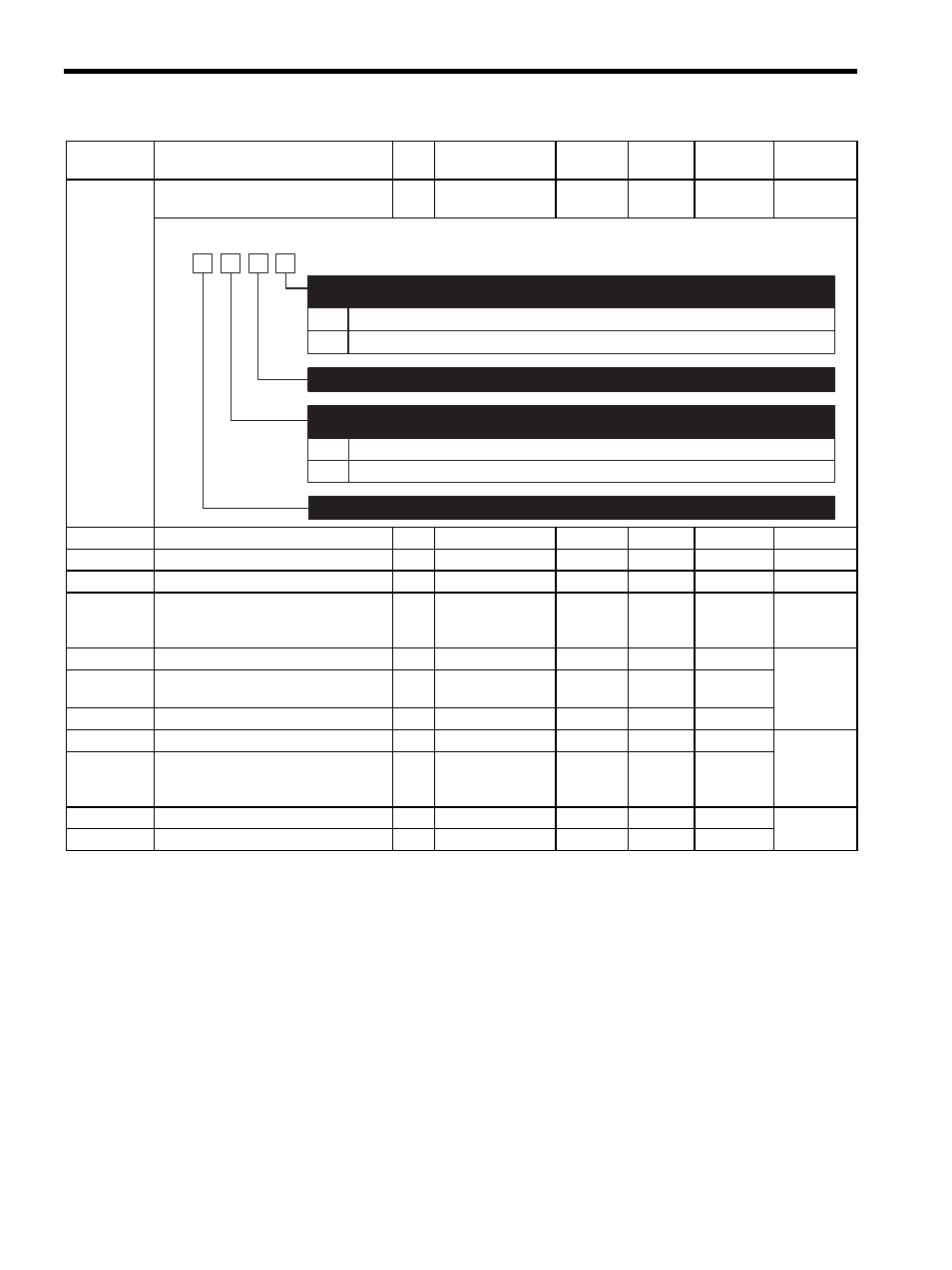
Pn008
Function Selection Application Switch
8
2
−
−
4000
∆
−
Pn100
Speed Loop Gain
2
1.0 to 2000.0 Hz
0.1 Hz
40.0 Hz
Pn101
Speed Loop Integral Time Constant
2
0.15 to 512.00 ms
0.01 ms
20.00 ms
Pn102
Position Loop Gain
2
1.0 to 2000.0/s
0.1/s
40.0/s
Pn103
Moment of Inertia Ratio
2
0 to 20000%
1%
0%
Pn104
2nd Speed Loop Gain
2
1.0 to 2000.0 Hz
0.1 Hz
40.0 Hz
Pn105
2nd Speed Loop Integral Time
Constant
2
0.15 to 512.00 ms
0.01 ms
20.00 ms
Pn106
2nd Position Loop Gain
2
1.0 to 2000.0/s
0.1/s
40.0/s
Pn107
Bias
2
0 to 450 RPM
1 RPM
0 RPM
Pn108
Bias Addition Width
2
0 to 250 reference
units
Reference
unit
7 refer-
ence
units
Pn109
Feed Forward Gain
2
0 to 100%
1%
0%
Pn10A
Feed Forward Filter Time Constant
2
0.00 to 64.00 ms
0.01 ms
0.00 ms
Note:
: Can be changed at any time, and immediately validated after changing. (Called an online
parameter.)
∆: Validated after a Set Up Device command is sent, when loading and using parameters at
power ON. Also validated when turning OFF and then ON the power supply again after a
Write Non-volatile Parameter (PPRM_WR) command is sent.
Parameter
No.
Name
Data
Size
Setting Range
Units
Factory
Setting
Changing
Method
Reference
Section
0
1
Outputs alarm (A.830) for lowered battery voltage.
Outputs warning (A.930) for lowered battery voltage.
Lowered Battery Voltage Alarm/Warning Selection
(Refer to "10.1.3 Warning Displays.")
Reserved (Do not change)
0
1
Detects warning.
Does not detect warning.
Warning Detection Selection
(Refer to "10.1.3 Warning Displays.")
4th
digit
3rd
digit
2nd
digit
1st
digit
n.
Reserved (Do not change)