Yaskawa SGDS Sigma III Servo Amplifier User Manual
Page 345
11 Appendix
11.2.2 List of Parameters
11-30
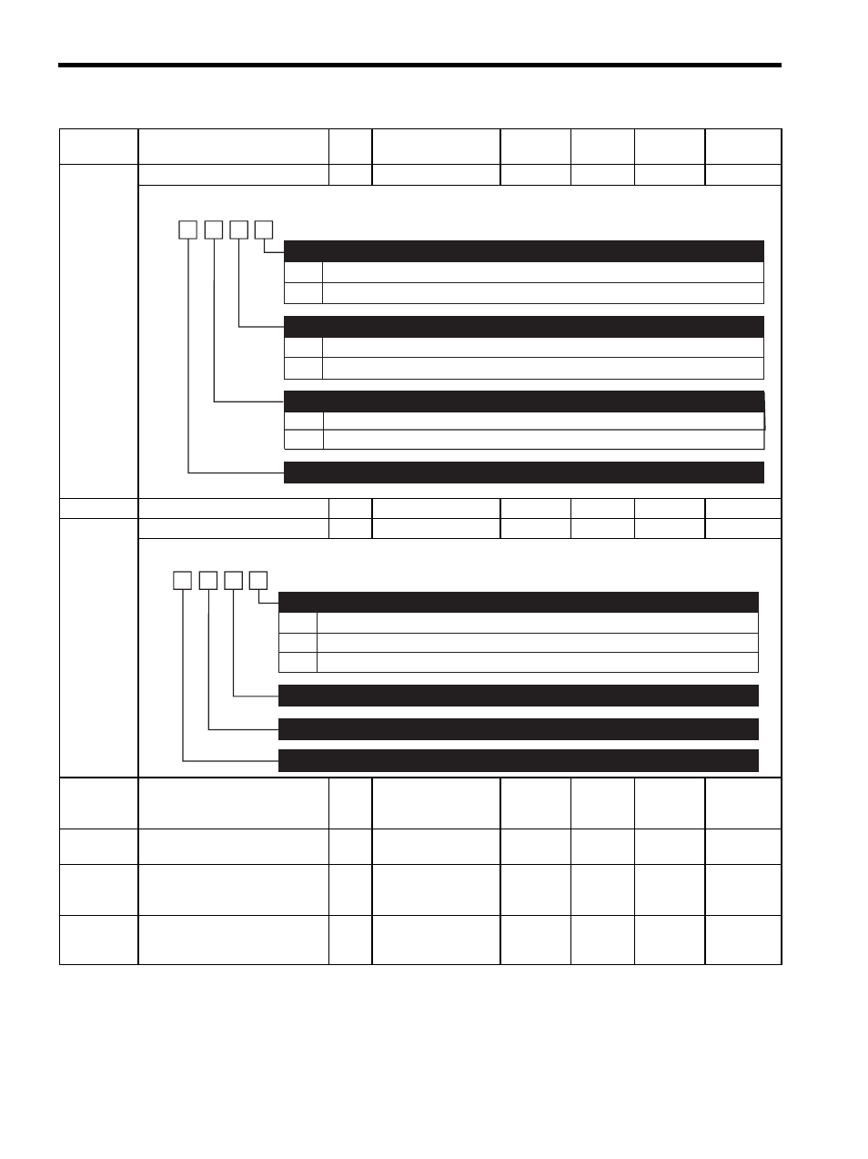
Pn512
Output Signal Reversal Setting
2
−
−
0000
∆
Pn513
Reserved (Do not change)
−
−
−
−
−
−
Pn515
Input Signal Selection 5
2
−
−
8888
∆
−
Pn51B
Excessive Error Level between
Motor and Load Position
4
0 to 1073741824
reference units
1 reference
unit
1000
reference
units
Pn51E
Excessive Position Error Warning
Level
2
10 to 100%
1%
100%
Pn520
Excessive Position Error Alarm
Level
4
1 to 1073741823
reference units
1 reference
unit
262144
reference
units
Pn522
Positioning Completion Width
4
0 to 1073741824
reference units
1 reference
unit
7
reference
units
Note:
: Can be changed at any time, and immediately validated after changing. (Called an online
parameter.)
∆: Validated after a Set Up Device command is sent, when loading and using parameters at
power ON. Also validated when turning OFF and then ON the power supply again after a
Write Non-volatile Parameter (PPRM_WR) command is sent.
Parameter
No.
Name
Data
Size
Setting Range
Unit
Factory
Setting
Changing
Method
Reference
Section
0
1
0
1
0
1
Output signal is not reversed.
Output signal is reversed.
Output signal is not reversed.
Output signal is reversed.
Output signal is not reversed.
Output signal is reversed.
Output Signal Reversal for CN1-1, 2 Terminals
4th
digit
3rd
digit
2nd
digit
1st
digit
n.
Output Signal Reversal for CN1-23, 24 Terminals
Output Signal Reversal for CN1-25, 26 Terminals
Reserved (Do not change)
0 to 7
8
9 to F
Reserved (Do not change)
Do not set. (Automatically sets to 8.)
Reserved (Do not change)
/G-SEL2 Signal Mapping
4th
digit
3rd
digit
2nd
digit
1st
digit
n.
Reserved (Do not change)
Reserved (Do not change)
Reserved (Do not change)