19 request latch mode (ltmod_on: 28h), 19 request latch mode (ltmod_on: 28h) -25 – Yaskawa SGDS Sigma III Servo Amplifier User Manual
Page 156
6.3 Main Commands
6-25
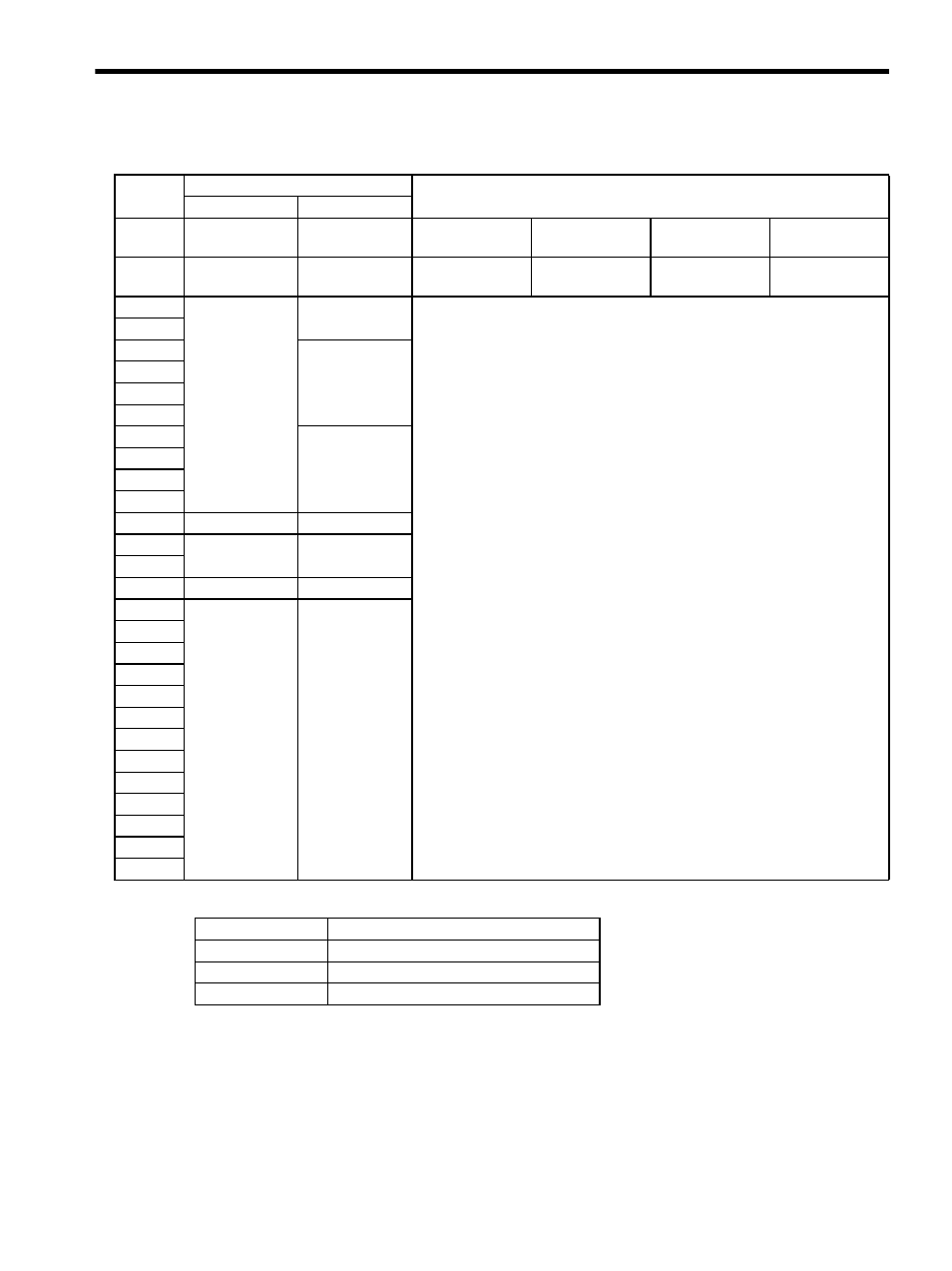
6.3.19 Request Latch Mode (LTMOD_ON: 28H)
• Related Parameters
Byte
LTMOD_ON
Description
Command
Response
1
28H
28H
Processing
classifications
Control com-
mand group
Synchronization
classifications
Asynchronous
2
LT_SGN
ALARM
Processing time
Within communi-
cations cycle
Subcommand
Can be used
3
STATUS
• Sets the modal latch mode. If a latch signal is input during modal latch mode,
position latching will be performed.
• Can be used during phases 2 and 3.
• During phase 1 Command warning 1 (A.95A) will occur and the command
will be ignored..
• A latch signal can be selected using LT_SGN. Refer to 6.5.1 Latch Signal
Field Specifications (LT_SGN).
• Use CMDRDY = 1 to confirm that the Request Latch Mode command has
been received.
• It takes 500
µs max. for the Request Latch Mode command to start.
• Confirm that L_CMP is 1 in STATUS at the completion of latching.
- When there is monitor data such as SMON or POSING appended to the
command response, LPOS is forcefully returned to MONITOR2 for one
communication cycle.
- When there is no monitor data such as PRM_RD or ALM_RD appended to
the command response, confirm that L_CMP is 1 in STATUS, then use a
command that has monitor data such as SMON in the response and select
LPOS to confirm.
• Once the latch operation has been performed, it will not be performed again
even if a latch signal is input. Send a new LTMOD_ON command.
• Interference with another latch mode command
- During the execution of a command such as LATCH, ZRET, EX_POSING,
or SVCTRL, the LTMOD_ON command cannot be used. If this command is
used during the execution of these commands, the warning Command
warning 4 (A.95D) will occur.
4
5
MONITOR1
6
7
8
9
MONITOR2
10
11
12
13
SEL_MON 1/2
SEL_MON 1/2
14
IO_MON
15
16
WDT
RWDT
17
For
subcommands.
Refer to 6.4
Subcommands.
For
subcommands.
Refer to 6.4
Subcommands.
18
19
20
21
22
23
24
25
26
27
28
29
Pn No.
Description
Pn511
Input Signal Selections 5
Pn820
Latching Area Upper Limit
Pn822
Latching Area Lower Limit