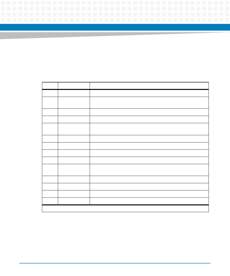
Table 7-49, Event message format, System management – Artesyn ATCA-9305 User's Manual (May 2014) User Manual
Page 206

System Management
ATCA-9305 User’s Manual (10009109-07)
206
Under certain circumstances, some sensors connected to the IPMC can generate Event
Messages for the system management controller. To enable these messages, the system
management controller must send a Set Event Receiver command to the IPMC, along with the
address of the Event Receiver.
shows the format of an Event Message:
Event-generating sensors with a Threshold Event/Reading Type (0x01) initiate an event
message when a sensor reading crosses the defined threshold. The default thresholds for a
particular sensor are retrieved by sending the IPMC a Get Sensor Thresholds command. The
system management controller must send the IPMC a Get Sensor Reading command to
retrieve the current sensor reading. Refer to the IPMI specification listed in
for
complete details on using these commands.
Table 7-49 Event Message Format
Byte
1
Field
Description
0
RsSA
Responder’s Slave Address (Address of Event Receiver)
1
NetFn/RsLUN
Net Function Code (0x04) in upper 6 bits; Responder’s LUN in lower 2
bits
2
Chk 1
Checksum #1
3
RqSA
Requester’s Slave Address (Address of our board on IPMB)
4
RqSeq/RqLUN
Request Sequence number in upper 6 bits; Requester’s LUN in lower 2
bits
5
Cmd
Command (Always 0x02 for event message)
6
EvMRev
Event Message Revision (0x04 for IPMI 1.5)
7
Sensor Type
Indicates event class or type of sensor that generated the message
8
Sensor Number
A unique number indicating the sensor that generated the message
9
Event D ir/Event
Type
Upper bit indicates direction (0 = Assert, 1= Deassert); Lower 7 bits
indicate type of threshold crossing or state transition
10
Event Data 0
Data for sensor and event type
11
Event Data 1
(Optional) Data for sensor and event type
12
Event Data 2
(Optional) Data for sensor and event type
13
Chk2
Checksum #2
Each byte has eight bits.
