Management processor cpld, 1 mpc8548 pld register summary, Table 5-1 – Artesyn ATCA-9305 User's Manual (May 2014) User Manual
Page 105: Pld register summary, Ribed in, Chapter 5, management processor, Cpld, Chapter 5
Chapter 5
ATCA-9305 User’s Manual (10009109-07)
105
Management Processor CPLD
5.1
MPC8548 PLD Register Summary
The ATCA-9305 uses a Programmable Logic Device (PLD) to provide control logic for the local
bus. The PLD implements various registers for reset, hardware, and LPC bus communication
between the processors.
The PLD registers start at address FC40, 000016. As a rule, registers retain their values through
all resets except for power-on and front panel reset.
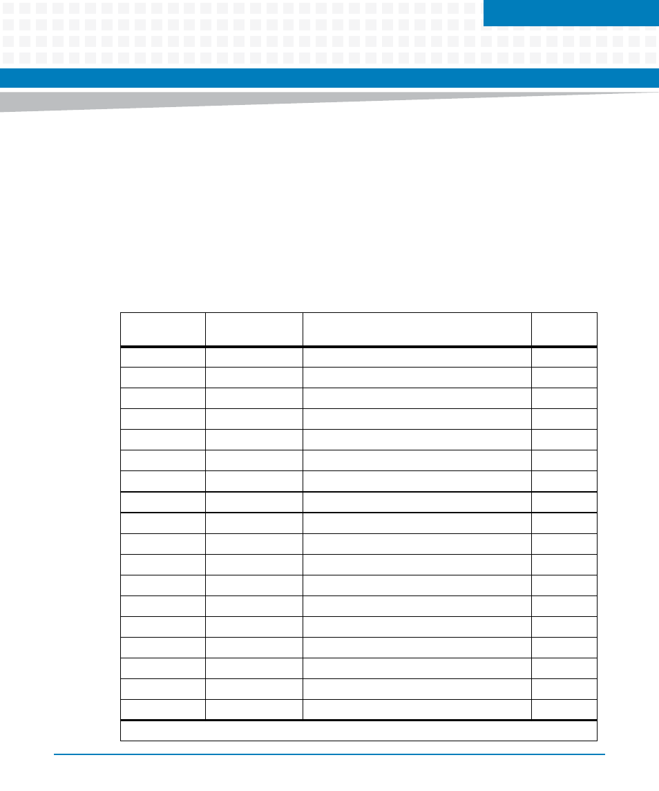
lists the 8-bit PLD registers
followed by the register bit descriptions.
Table 5-1 PLD Register Summary
Address Offset
(hex)
Mnemonic
Register Name
See Page
0x00
PIDR
Product ID
0x04
HVR
Hardware Version
0x08
PVR
PLD Version
0x0C
PLLCR
PLL Configuration
0x10
HCR00
Hardware Configuration 0
0x18
JSR
Jumper Setting
0x1C
LEDR
LED
0x20
RER
Reset Event
0x24
RCR1
Reset Command #1
0x28
RCR2
Reset Command #2
0x2C
RCR3
Reset Command #3
0x30
RCR4
Reset Command #4
0x34
RCR5
Reset Command #5
0x38
RCRS1
Reset Command Sticky #1
0x3C
RCRS2
Reset Command Sticky #2
0x40
SCR1
Scratch #1
1
-
0x50
BDRR
Boot Device Redirection
0x54
MISC
Miscellaneous Control (SIO, I2C, Test Clock)
Scratch 1 (0x40) is a read/write register for storage only.