5 management processor header and serial port, 1 jtag/cop interface (optional), Table 4-7 – Artesyn ATCA-9305 User's Manual (May 2014) User Manual
Page 103: Serial debug connector, p2, Management complex
Management Complex
ATCA-9305 User’s Manual (10009109-07)
103
4.5
Management Processor Header and Serial Port
4.5.1
JTAG/COP Interface (optional)
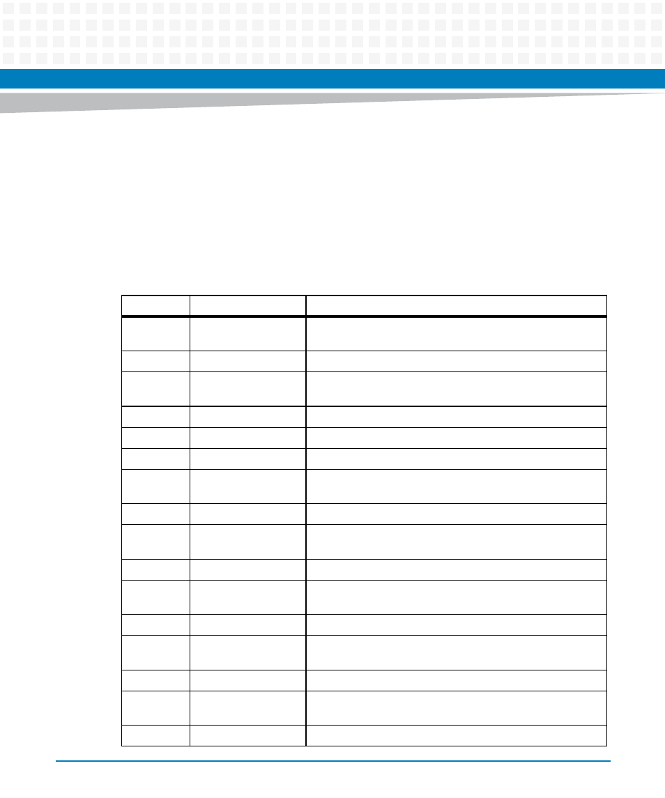
The management complex uses header P2 for debug purposes.
Table 4-7 Serial Debug Connector, P2
Pin
Signal
Description
1
PQ_TDO
Test Data Output is the serial data output as well as test and
programming data.
2
no connect
-
3
PQ_TDI
Test Data Input is the serial input pin for instructions as well as
test and programming data.
4
DEBUG_TRST*
Test Reset input signal resets the test access port.
5
no connect
-
6
PQ_JTAG_PWR
3.3 volt power
7
PQ_TCK_R
Test Clock Input is the clock input to the boundary scan test
(BST) circuitry.
8
no connect
—
9
PQ_TMS
Test Mode Select input pin provides the control signal to
determine the transitions of the TAP controller state machine.
10
no connect
-
11
DEBUG_SRESET*
Soft Reset input signal indicates that the MPC8548 must
initiate a System Reset interrupt.
12
ground
-
13
DEBUG_HRESET*
Hard Reset input signal indicates that a complete Power-on
Reset must be initiated by the MPC8548.
14
no connect
-
15
PQ_CKSTP_OUT*
Checkstop Out indicates the MPC8548 has detected a
checkstop condition and has ceased operation.
16
ground
-