25 cavium gpio control, 26 cavium gpio data out, 25 cavium gpio control 5.1.26 cavium gpio data out – Artesyn ATCA-9305 User's Manual (May 2014) User Manual
Page 123: Table 5-26, Cavium gpio control (0x80), Table 5-27, Cavium gpio data out (0x84), Management processor cpld
Management Processor CPLD
ATCA-9305 User’s Manual (10009109-07)
123
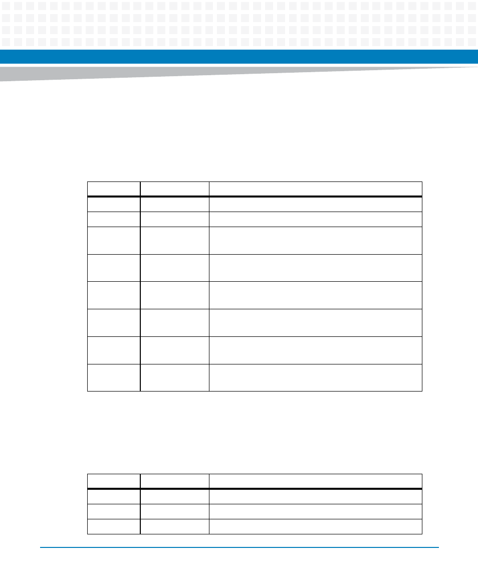
5.1.25 Cavium GPIO Control
Each Cavium processor has three GPIO control bits connected to the PLD. This register
determines whether the PLD is driving or receiving on these lines. Setting a bit to 1 causes the
PLD to drive the corresponding line.
5.1.26 Cavium GPIO Data Out
This register is the data that will be driven on the GPIO line when the Output enable is set.
Table 5-26 Cavium GPIO Control (0x80)
Bits
Function
Description
7
reserved
6
reserved
5
P2GPIO5OE
Processor 2 GPIO5 Output Enable (enabled is the default)
Output enable is set for the TIC timer output to the Cavium
4
P2GPIO4OE
Processor 2 GPIO4 Output Enable
This is an input from the Cavium to reset the MIP4
3
P2GPIO3OE
Processor 2 GPIO3 Output Enable
This is an input from the Cavium to reset the MIP3
2
P1GPIO5OE
Processor 1 GPIO5 Output Enable (enabled is the default)
Output enable is set for the TIC timer output to the Cavium
1
P1GPIO4OE
Processor 1 GPIO4 Output Enable
This is an input from the Cavium to reset the MIP2
0
P1GPIO3OE
Processor 1 GPIO3 Output Enable
This is an input from the Cavium to reset the MIP1
Table 5-27 Cavium GPIO Data Out (0x84)
Bits
Function
Description
7
reserved
6
reserved
5
reserved