Delta Electronics Elevator Drive VFD-VL User Manual
Page 96
Chapter 4 Parameters|
Revision Nov. 2008, VLE1, SW V1.03 4-41
Settings
Functions
Descriptions
41 Reserved
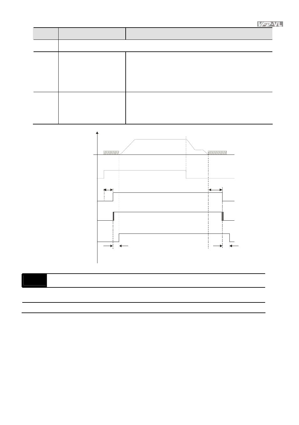
42 Mechanical
brake
When drive receives RUN command, the corresponding
output terminal (setting 12) will be enabled after Pr.02-
29 time. It will check if this function is enabled within the
detection time (Pr.02-35). If NOT, the fault of mechanical
brake occurs and fault code “MBF” will be displayed.
43 EPS
function
If power is cut during running, the drive will stop when
DC bus voltage is less than low voltage level. After
power is cut, drive will run by the frequency depend on
EPS when EPS is applied and this function is ON.
F requenc y
Time
07-03
07-04
02-29
02-30
frequency
output
operation
command
(F WD/RE V)
multi-function
output ter minal
d=12
mechanical
brake
multi-function
input terminal
d=42
T 1< 02- 35
T 2< 02- 35
02-09
Digital Input Response Time
Unit: 0.001
Control
mode
VF
VFPG
SVC
FOCPG TQCPG FOCPM
Factory setting: 0.005
Settings
0.001~ 30.000 sec
This parameter is used for digital input terminal signal delay and confirmation. The delay time
is confirmation time to prevent some uncertain interferences that would result in error (except
for the counter input) in the input of the digital terminals (FWD, REV and MI1~8). Under this
condition, confirmation for this parameter could be improved effectively, but the response time
will be somewhat delayed.