Delta Electronics Elevator Drive VFD-VL User Manual
Page 28
Chapter 2 Installation and Wiring|
Revision Nov. 2008, VLE1, SW V1.03 2-3
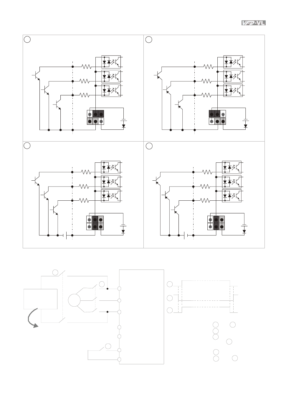
Figure 2 Wiring/Terminals setting for SINK(NPN) mode and SOURCE(PNP) mode
3
1
Sink (NPN) mode
Source (PNP) mode
2
4
Sink (NPN) mode
Source (PNP) mode
used with internal power (+24Vdc)
used with internal power (+24Vdc)
used with external power
used with external power
COM
MI1
+24V
MI2
MI8
~
COM
MI1
+24V
MI2
MI8
~
COM
MI1
+24V
+
MI2
MI8
~
COM
MI1
+24V
+
MI2
MI8
~
250VDC (for 230V ser ies)
500VDC (for 460V ser ies)
3
~
EPS/+
R/L1
S/L2
T /L3
EPS/-
MI1~8
COM
1
2
3
1
2
3
AC motor driv e
Timing diagr am of M.C.
(
magnetic contac t or)
Main power
1-phase UP S
or battery
Specifications for
1-phase UP S and battery
Figure 3 Apply to 1-phase UPS power supply system
To input emergency power
Before i nputting emergency power,
magnetic c ontactor and ar e ON and
magnetic c ontactor s hould be O FF.
Magnetic c ontactor s hould be O N
after magnetic c ontactor is ON.
Before r emoving battery and turn
magnetic c ontactor to be ON,
magnetic c ontactor and shoul d be
OF F.
1
3
1
3
2
3
1
2
- 1x9 Bi-Directional Transceiver Module OPBD-155F2J1R (7 pages)
- Single Mode SFP Transceiver LCP-1250B4MDRx (14 pages)
- LC-1250xxxx Series (10 pages)
- Human Machine Interface DOP-AS Series (329 pages)
- Analog Output Module DVP04DA-S (2 pages)
- DeviceNet Slave Communication Module IFD9502 (2 pages)
- LCP-155B4MSRx (12 pages)
- High-Speed PCI 12-Axis Motion Control Card PCI-DMC-B01 (528 pages)
- Network Device DVP01PU-S (2 pages)
- GBIC-1250D5MR (12 pages)
- SPBD-1250A4Q1RT (10 pages)
- SILM4015 (1 page)
- LCP-8500A4EDR (14 pages)
- 10GBASE-SR SFP+ Optical Transceiver LCP-10G3A4EDR (16 pages)
- LCP-155A4HSRx (11 pages)
- LCP-1250RJ3SR-L (9 pages)
- SILM320L (1 page)
- LCP-1250RJ3SR-S (9 pages)
- SIL530 (1 page)
- Extension Digital I/O Module DOP-EXIO28RAE (1 page)
- DVP Series PLC DVP04TC-H2 (2 pages)
- 1x9 Bi-Directional Transceiver Module OPBD-155F1J1R (7 pages)
- Distribution Box TAP-CN01/02/03 (2 pages)
- LCP-200A4HSR (9 pages)
- Pulse Generation Unit DVP01PU-H2 (2 pages)
- Power Connection Interface VFD-PSD01 (1 page)
- Programmable Logic Controller DVP04DA-H2 (2 pages)
- Single Mode SFP Transceiver LCP-1250B4QDRx (13 pages)
- LCP-155B4JSRx Series (12 pages)
- Series Temperature Controller DTD Series (2 pages)
- Brake Modules BUE Series (2 pages)
- PLC DVP Series DVP-SX (2 pages)
- Digital Keypad / Display ASD-PU-01A (1 page)
- Multimode SFP Transceiver LCP-1250A4FDRx (14 pages)
- HMU1362M (1 page)
- RPA-01 (1 page)
- THMR1395 (1 page)
- SFBD-155F2J1RM (7 pages)
- Program Transfer Module DVP-PCC01 (1 page)
- RTU-DNET (41 pages)
- AC Servo Drive ASDA-AB (37 pages)
- Digital Keypad / Display ASD-PU-01B (1 page)
- HMR1045 (1 page)
- CANopen Communication Module DVPCOPM-SL (2 pages)
- SPBD-1250B4Q1R (10 pages)