4 control terminals, 4 control terminals -10, The position of external terminals – Delta Electronics Elevator Drive VFD-VL User Manual
Page 35
Chapter 2 Installation and Wiring|
2-10
Revision Nov. 2008, VLE1, SW V1.03
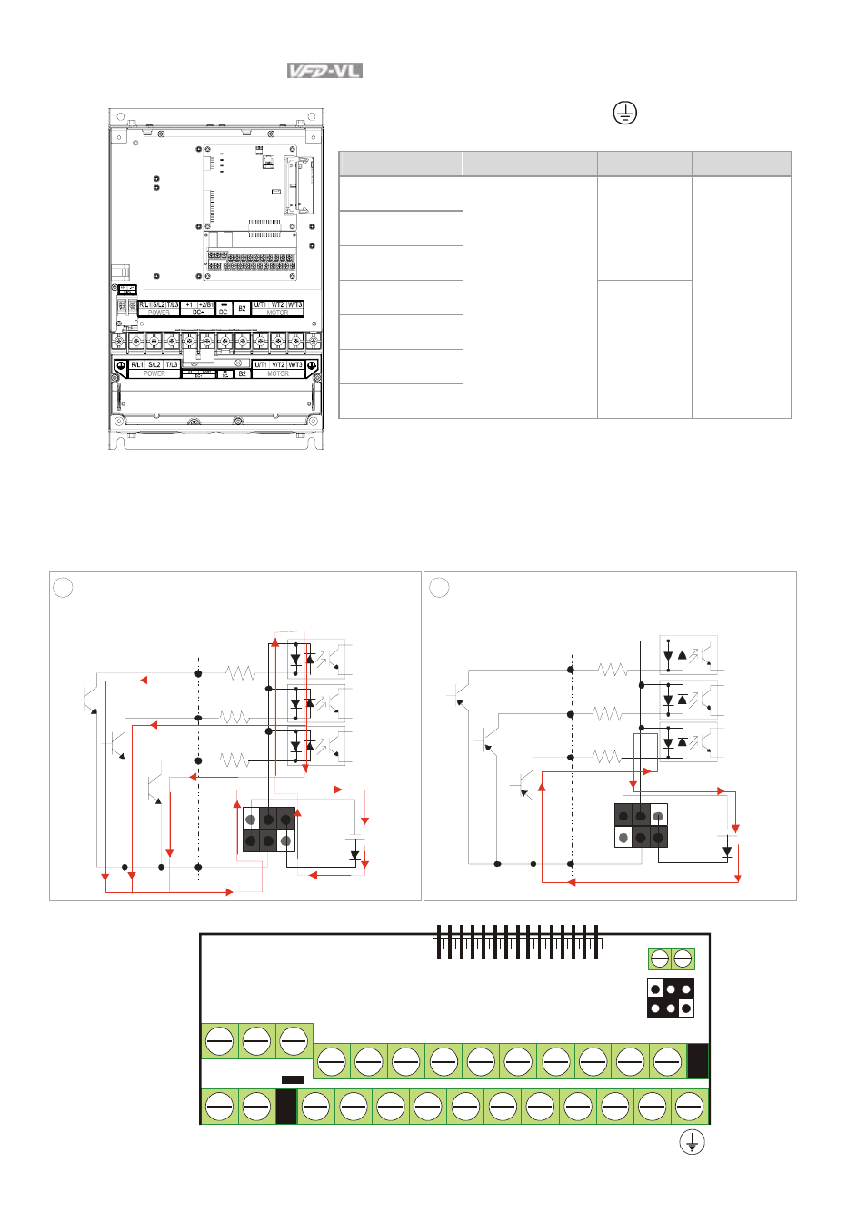
Frame E
Main circuit terminals
R/L1, S/L2, T/L3, U/T1, V/T2, W/T3,
, +1, +2, -
Models
Wire
Torque
Wire Type
VFD300VL43A
VFD370VL43A
VFD450VL43A
57kgf-cm
(49in-lbf)
VFD300VL23A
VFD370VL23A
VFD550VL43A
VFD750VL43A
4-2 AWG.
(21.2-33.6mm2)
200kgf-cm
(173in-lbf)
Stranded
copper only,
75
o
C
2.4 Control Terminals
1
Sink /NPN Mode
COM
MI1
+2 4V
MI2
MI8
~
Source Mode
2
COM
MI1
+2 4V
MI2
MI8
~
u se d w it h in ternal pow er (+24 Vdc)
The Position of External Terminals
+10V
MO1 MO2
MI3
MI4
MI7
MI6
COM
ACM
AUI1
ACI
MCM
MRC
RA
MRA
RC
RB
REV
MI2
FWD
MI1
AUI2
MI5
MI8
-10V
Sink/Source
mode switch
+E24V
DCM
See also other documents in the category Delta Electronics Hardware:
- 1x9 Bi-Directional Transceiver Module OPBD-155F2J1R (7 pages)
- Single Mode SFP Transceiver LCP-1250B4MDRx (14 pages)
- LC-1250xxxx Series (10 pages)
- Human Machine Interface DOP-AS Series (329 pages)
- Analog Output Module DVP04DA-S (2 pages)
- DeviceNet Slave Communication Module IFD9502 (2 pages)
- LCP-155B4MSRx (12 pages)
- High-Speed PCI 12-Axis Motion Control Card PCI-DMC-B01 (528 pages)
- Network Device DVP01PU-S (2 pages)
- GBIC-1250D5MR (12 pages)
- SPBD-1250A4Q1RT (10 pages)
- SILM4015 (1 page)
- LCP-8500A4EDR (14 pages)
- 10GBASE-SR SFP+ Optical Transceiver LCP-10G3A4EDR (16 pages)
- LCP-155A4HSRx (11 pages)
- LCP-1250RJ3SR-L (9 pages)
- SILM320L (1 page)
- LCP-1250RJ3SR-S (9 pages)
- SIL530 (1 page)
- Extension Digital I/O Module DOP-EXIO28RAE (1 page)
- DVP Series PLC DVP04TC-H2 (2 pages)
- 1x9 Bi-Directional Transceiver Module OPBD-155F1J1R (7 pages)
- Distribution Box TAP-CN01/02/03 (2 pages)
- LCP-200A4HSR (9 pages)
- Pulse Generation Unit DVP01PU-H2 (2 pages)
- Power Connection Interface VFD-PSD01 (1 page)
- Programmable Logic Controller DVP04DA-H2 (2 pages)
- Single Mode SFP Transceiver LCP-1250B4QDRx (13 pages)
- LCP-155B4JSRx Series (12 pages)
- Series Temperature Controller DTD Series (2 pages)
- Brake Modules BUE Series (2 pages)
- PLC DVP Series DVP-SX (2 pages)
- Digital Keypad / Display ASD-PU-01A (1 page)
- Multimode SFP Transceiver LCP-1250A4FDRx (14 pages)
- HMU1362M (1 page)
- RPA-01 (1 page)
- THMR1395 (1 page)
- SFBD-155F2J1RM (7 pages)
- Program Transfer Module DVP-PCC01 (1 page)
- RTU-DNET (41 pages)
- AC Servo Drive ASDA-AB (37 pages)
- Digital Keypad / Display ASD-PU-01B (1 page)
- HMR1045 (1 page)
- CANopen Communication Module DVPCOPM-SL (2 pages)
- SPBD-1250B4Q1R (10 pages)