Delta Electronics Elevator Drive VFD-VL User Manual
Page 101
Chapter 4 Parameters|
4-46
Revision Nov. 2008, VLE1, SW V1.03
Settings
Functions
Descriptions
40
Speed Attained
(including zero speed)
Active when the output frequency reaches frequency setting.
41 Reserved
02-23
Multi-output Direction
Unit:1
Control
mode
VF
VFPG
SVC
FOCPG TQCPG FOCPM
Factory setting: 0
Settings
0 ~ 65535
This parameter is bit setting. If the bit is 1, the multi-function output terminal will be act with
opposite direction. For example, if Pr.02-11 is set to 1 and forward bit is 0, Relay 1 will be ON
when the drive is running and OFF when the drive is stop.
The multi-function output terminals MO3~MO10 need to use with EMVL-IODA01.
Bit 11 Bit 10 Bit 9 Bit 8 Bit 7 Bit 6 Bit 5 Bit 4 Bit 3 Bit 2 Bit 1 Bit 0
MO10 MO9 MO8 MO7 MO6 MO5 MO4 MO3 MO2 MO1 MRA
RA
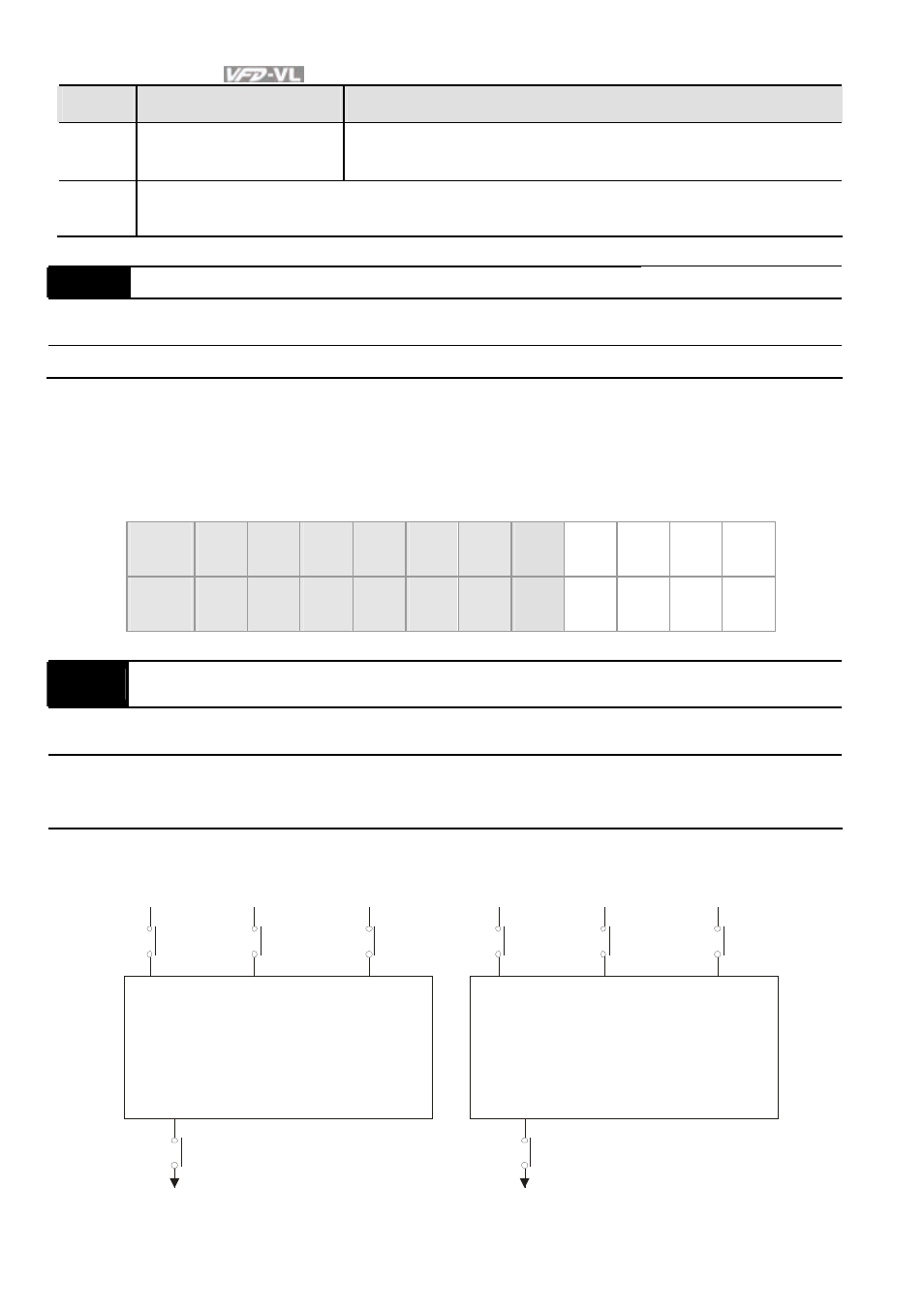
02-24
Serial Start Signal Selection
Control
mode
VF
VFPG
SVC
FOCPG FOCPM
Factory setting: 0
Settings
0
by
FWD/REV
1
by Enable
This parameter is used to select serial start method of electromagnetic valve.
Enable
FWD
MC1
Multifunction
output MO=15
MI=40
Multifunction
input
MC1
Enable
FWD
REV
MC1
REV
MC1
When setting to 0
When setting to 1
forward
running
rev er se
running
forward
running
rev er se
running
MI=40
Multifunction
input
Multifunction
output MO=15
Electr omagnetic valve
Electr omagnetic valve