Delta Electronics Elevator Drive VFD-VL User Manual
Page 153
Chapter 4 Parameters|
4-98
Revision Nov. 2008, VLE1, SW V1.03
Setting of PG
signal type
PG signal type
Applicable PG card
Pr.08-00=1
Pr.08-00=3
10-00=4
SIN/COS+Endat
EMVL-PGS01
Motor will run Motor won’t run
10-00=5
SIN/COS
EMVL-PGH01/02
Motor will run
Motor will run
10-00=6
SIN/COS +
Hiperface
EMVL-PGS01
Motor will run Motor won’t run
10-01
Encoder Pulse
Unit: 1
Control
mode
VFPG
FOCPG
TQCPG FOCPM
Factory Setting: 600
Settings
1 to 20000
A Pulse Generator (PG) or encoder is used as a sensor that provides a feedback signal of the
motor speed. This parameter defines the number of pulses for each cycle of the PG control.
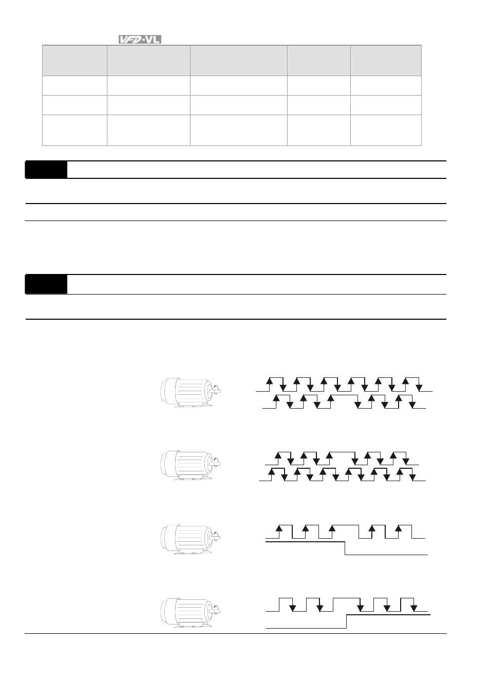
10-02
Encoder Input Type Setting
Control
mode
VFPG
FOCPG
TQCPG FOCPM
Factory Setting: 0
Settings
0
Disable
1
Phase A leads in a forward run command and phase B leads in a
reverse run command
For war d
running
A
B
FWD
REV
2
Phase B leads in a forward run command and phase A leads in a
reverse run command
For war d
running
A
B
FWD
REV
3
Phase A is a pulse input and phase B is a direction input. (low
input=reverse direction, high input=forward direction)
For war d
running
A
B
FWD
REV
4
Phase A is a pulse input and phase B is a direction input. (low
input=forward direction, high input=reverse direction)
For war d
running
A
B
FWD
REV