Delta Electronics Elevator Drive VFD-VL User Manual
Page 37
Chapter 2 Installation and Wiring|
2-12
Revision Nov. 2008, VLE1, SW V1.03
Terminal
Symbol
Terminal Function
Factory Settings (SINK)
ON: Connect to DCM
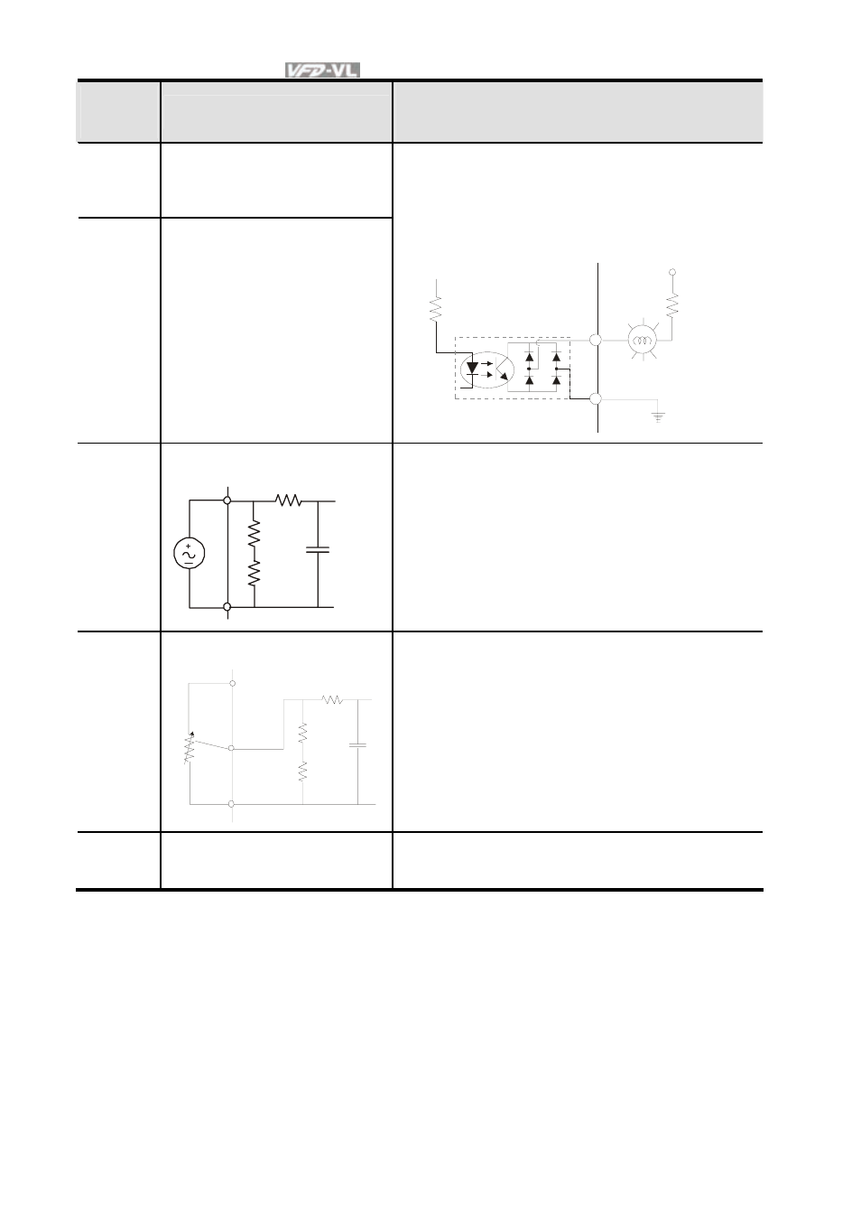
MO1
Multi-function Output 1
(Photocoupler)
MO2
Multi-function Output 2
(Photocoupler)
The AC motor drive output every monitor signal,
such as operational, frequency attained,
overload, etc. by open collector transistor. Refer
to Pr.03.01 multi-function output terminals for
details.
M O1
~
M O2
MCM
Max: 48Vdc/50m A
internal circuit
ACI
Analog current Input
ACM
ACI
internal circuit
ACI circuit
Impedance: 250Ω
Resolution: 12
bits
Range:
4 ~ 20mA/0~10V =
0 ~ Max. Output Frequency
(Pr.01-00)
Set-up:
Pr.03-00 ~ Pr.03-02
AUI1/
AUI2
Auxiliary analog voltage input
+10V
|
-10V
AUI
ACM
AUI circuit
internal circuit
Impedance: 2mΩ
Resolution: 12
bits
Range:
-10 ~ +10VDC =
0 ~ Max. Output Frequency
(Pr.01-00)
Set-up:
Pr.03-00 ~ Pr.03-02
ACM
Analog control signal
(common)
Common for ACI, AUI1, AUI2
*Control signal wiring size: 18 AWG (0.75 mm
2
) with shielded wire.
Analog input terminals (ACI, AUI1, AUI2, ACM)
- 1x9 Bi-Directional Transceiver Module OPBD-155F2J1R (7 pages)
- Single Mode SFP Transceiver LCP-1250B4MDRx (14 pages)
- LC-1250xxxx Series (10 pages)
- Human Machine Interface DOP-AS Series (329 pages)
- Analog Output Module DVP04DA-S (2 pages)
- DeviceNet Slave Communication Module IFD9502 (2 pages)
- LCP-155B4MSRx (12 pages)
- High-Speed PCI 12-Axis Motion Control Card PCI-DMC-B01 (528 pages)
- Network Device DVP01PU-S (2 pages)
- GBIC-1250D5MR (12 pages)
- SPBD-1250A4Q1RT (10 pages)
- SILM4015 (1 page)
- LCP-8500A4EDR (14 pages)
- 10GBASE-SR SFP+ Optical Transceiver LCP-10G3A4EDR (16 pages)
- LCP-155A4HSRx (11 pages)
- LCP-1250RJ3SR-L (9 pages)
- SILM320L (1 page)
- LCP-1250RJ3SR-S (9 pages)
- SIL530 (1 page)
- Extension Digital I/O Module DOP-EXIO28RAE (1 page)
- DVP Series PLC DVP04TC-H2 (2 pages)
- 1x9 Bi-Directional Transceiver Module OPBD-155F1J1R (7 pages)
- Distribution Box TAP-CN01/02/03 (2 pages)
- LCP-200A4HSR (9 pages)
- Pulse Generation Unit DVP01PU-H2 (2 pages)
- Power Connection Interface VFD-PSD01 (1 page)
- Programmable Logic Controller DVP04DA-H2 (2 pages)
- Single Mode SFP Transceiver LCP-1250B4QDRx (13 pages)
- LCP-155B4JSRx Series (12 pages)
- Series Temperature Controller DTD Series (2 pages)
- Brake Modules BUE Series (2 pages)
- PLC DVP Series DVP-SX (2 pages)
- Digital Keypad / Display ASD-PU-01A (1 page)
- Multimode SFP Transceiver LCP-1250A4FDRx (14 pages)
- HMU1362M (1 page)
- RPA-01 (1 page)
- THMR1395 (1 page)
- SFBD-155F2J1RM (7 pages)
- Program Transfer Module DVP-PCC01 (1 page)
- RTU-DNET (41 pages)
- AC Servo Drive ASDA-AB (37 pages)
- Digital Keypad / Display ASD-PU-01B (1 page)
- HMR1045 (1 page)
- CANopen Communication Module DVPCOPM-SL (2 pages)
- SPBD-1250B4Q1R (10 pages)