Delta Electronics Elevator Drive VFD-VL User Manual
Page 157
Chapter 4 Parameters|
4-102
Revision Nov. 2008, VLE1, SW V1.03
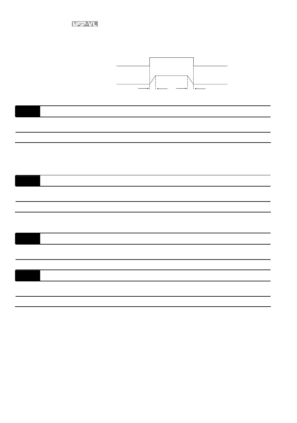
When using multi-function input terminals to switch ASR1/ASR2, the diagram will be shown as
follows.
ON
OFF
ASR 1
0.1 sec
OFF
0.1 sec
ASR 1
ASR 2
Setting multi-function input terminal to 17
(ASR1/ASR2 switch)
10-18
ASR Primary Low Pass Filter Gain
Unit: 0.001
Control
mode
VF
VFPG
SVC
FOCPG FOCPM
Factory Setting: 0.008
Settings
0.000 to 0.350 sec
It defines the filter time of the ASR command.
When setting to 1, this function is disabled.
10-19
Zero Speed Gain (P)
Unit: 0.01
Control
mode
FOCPM
Factory Setting: 80.00
Settings
0.00 to 655.00%
When Pr.11-00 is set to Bit 7=1, Pr.10-19 is valid.
10-20
Zero Speed/ASR1 Width Adjustment
Unit: 0.01
Control
mode
VFPG
FOCPG
FOCPM
Factory Setting: 5.00
Settings
0.0
to
120.00Hz
10-21
ASR1/ASR2 Width Adjustment
Unit: 0.01
Control
mode
VFPG
FOCPG
FOCPM
Factory Setting: 5.00
Settings
0.0
to
120.00Hz
These two parameters are used to decide width of slope of ASR command during zero speed
to low speed or Pr.10-17 to high speed.
- 1x9 Bi-Directional Transceiver Module OPBD-155F2J1R (7 pages)
- Single Mode SFP Transceiver LCP-1250B4MDRx (14 pages)
- LC-1250xxxx Series (10 pages)
- Human Machine Interface DOP-AS Series (329 pages)
- Analog Output Module DVP04DA-S (2 pages)
- DeviceNet Slave Communication Module IFD9502 (2 pages)
- LCP-155B4MSRx (12 pages)
- High-Speed PCI 12-Axis Motion Control Card PCI-DMC-B01 (528 pages)
- Network Device DVP01PU-S (2 pages)
- GBIC-1250D5MR (12 pages)
- SPBD-1250A4Q1RT (10 pages)
- SILM4015 (1 page)
- LCP-8500A4EDR (14 pages)
- 10GBASE-SR SFP+ Optical Transceiver LCP-10G3A4EDR (16 pages)
- LCP-155A4HSRx (11 pages)
- LCP-1250RJ3SR-L (9 pages)
- SILM320L (1 page)
- LCP-1250RJ3SR-S (9 pages)
- SIL530 (1 page)
- Extension Digital I/O Module DOP-EXIO28RAE (1 page)
- DVP Series PLC DVP04TC-H2 (2 pages)
- 1x9 Bi-Directional Transceiver Module OPBD-155F1J1R (7 pages)
- Distribution Box TAP-CN01/02/03 (2 pages)
- LCP-200A4HSR (9 pages)
- Pulse Generation Unit DVP01PU-H2 (2 pages)
- Power Connection Interface VFD-PSD01 (1 page)
- Programmable Logic Controller DVP04DA-H2 (2 pages)
- Single Mode SFP Transceiver LCP-1250B4QDRx (13 pages)
- LCP-155B4JSRx Series (12 pages)
- Series Temperature Controller DTD Series (2 pages)
- Brake Modules BUE Series (2 pages)
- PLC DVP Series DVP-SX (2 pages)
- Digital Keypad / Display ASD-PU-01A (1 page)
- Multimode SFP Transceiver LCP-1250A4FDRx (14 pages)
- HMU1362M (1 page)
- RPA-01 (1 page)
- THMR1395 (1 page)
- SFBD-155F2J1RM (7 pages)
- Program Transfer Module DVP-PCC01 (1 page)
- RTU-DNET (41 pages)
- AC Servo Drive ASDA-AB (37 pages)
- Digital Keypad / Display ASD-PU-01B (1 page)
- HMR1045 (1 page)
- CANopen Communication Module DVPCOPM-SL (2 pages)
- SPBD-1250B4Q1R (10 pages)