Delta Electronics Elevator Drive VFD-VL User Manual
Page 86
Chapter 4 Parameters|
Revision Nov. 2008, VLE1, SW V1.03 4-31
01-05
01-03
01-01
01-06
01-04
01-02
01-00
01-07
01-08
01-09
01-11
01-10
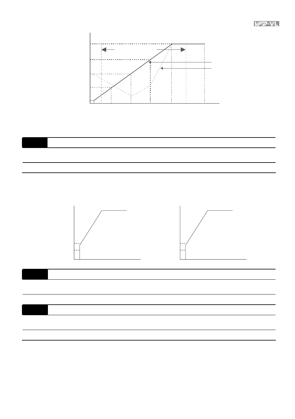
1st Output
Voltage Setting 1
Output Frequency
Lower Limit
Frequency output
ranges limitation
Regular V/f Curve
Special V/f Curve
Voltage
4th Freq.
Start Freq.
3rd Freq.
2nd Freq.
1st Freq.
Maximum Output
Frequency
V/f Curve
2nd Output
Voltage Setting 1
3rd Output
Voltage Setting 1
4th Output
Voltage Setting 1
Output Frequency
Upper Limit
Frequency
01-09
Start Frequency
Unit: 0.01
Control
mode
VF
VFPG
SVC
FOCPG
Factory setting: 0.50
Settings
0.00~120.00Hz
To distinguish which frequency should be start frequency, it needs to compare the value of min.
output frequency and start frequency. The larger value will be start frequency.
When min. output frequency > start frequency
When start frequency > min. output frequency
min. output
frequency
start frequency
start frequency
min. output
frequency
01-10
Output Frequency Upper Limit
Unit: 0.01
Control
mode
VF
VFPG
SVC
FOCPG FOCPM
Factory setting: 120.00
Settings
0.00~120.00Hz
01-11
Output Frequency Lower Limit
Unit: 0.01
Control
mode
VF
VFPG
SVC
FOCPG FOCPM
Factory setting: 0.00
Settings
0.00~120.00Hz
The upper/lower output frequency setting is used to limit the actual output frequency. If the
frequency setting is lower than the start-up frequency, it will run with zero speed. If the
frequency setting is higher than the upper limit, it will runs with the upper limit frequency. If
output frequency lower limit > output frequency upper limit, this function is invalid.