Delta Electronics Elevator Drive VFD-VL User Manual
Page 63
Chapter 4 Parameters|
4-8
Revision Nov. 2008, VLE1, SW V1.03
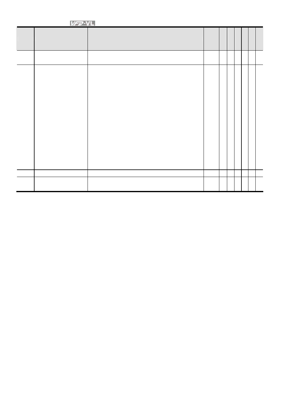
Pr.
Explanation
Settings
Factory
Setting
VF
VF
PG
SVC
FOC
PG
TQC
PG
FOC
PM
03-19
Analog Output Value in REV
Direction 1
0: Absolute value in REV direction
1: Output 0V in REV direction
2: Enable output voltage in REV direction
0
○ ○ ○ ○ ○ ○
03-20
Analog Output Selection 2
0: Output frequency (Hz)
0
○ ○ ○ ○ ○ ○
1: Frequency command (Hz)
○ ○ ○ ○ ○ ○
2: Motor speed (RPM)
○ ○ ○ ○ ○ ○
3: Output current (rms)
○ ○ ○ ○ ○ ○
4:
Output
voltage
○ ○ ○ ○ ○ ○
5: DC Bus Voltage
○ ○ ○ ○ ○ ○
6: Power factor
○ ○ ○ ○ ○ ○
7:
Power
○ ○ ○ ○ ○ ○
8: Output torque
○ ○ ○ ○ ○ ○
9:
AVI
○ ○ ○ ○ ○ ○
10:
ACI
○ ○ ○ ○ ○ ○
11:
AUI
○ ○ ○ ○ ○ ○
12: q-axis current
○ ○ ○ ○ ○ ○
13: q-axis feedback value
○ ○ ○ ○ ○ ○
14: d-axis current
○ ○ ○ ○ ○ ○
15: d-axis feedback value
○ ○ ○ ○ ○ ○
16: q-axis voltage
○ ○ ○ ○ ○ ○
17: d-axis voltage
○ ○ ○ ○ ○ ○
18: Torque command
○ ○ ○ ○ ○ ○
19-20:
Reserved
03-21
Analog Output Gain 2
0~200.0%
100.0
○ ○ ○ ○ ○ ○
03-22
Analog Output Value in REV
Direction 2
0: Absolute value in REV direction
1: Output 0V in REV direction
2: Enable output voltage in REV direction
0
○ ○ ○ ○ ○ ○