Delta Electronics Elevator Drive VFD-VL User Manual
Page 77
Chapter 4 Parameters|
4-22
Revision Nov. 2008, VLE1, SW V1.03
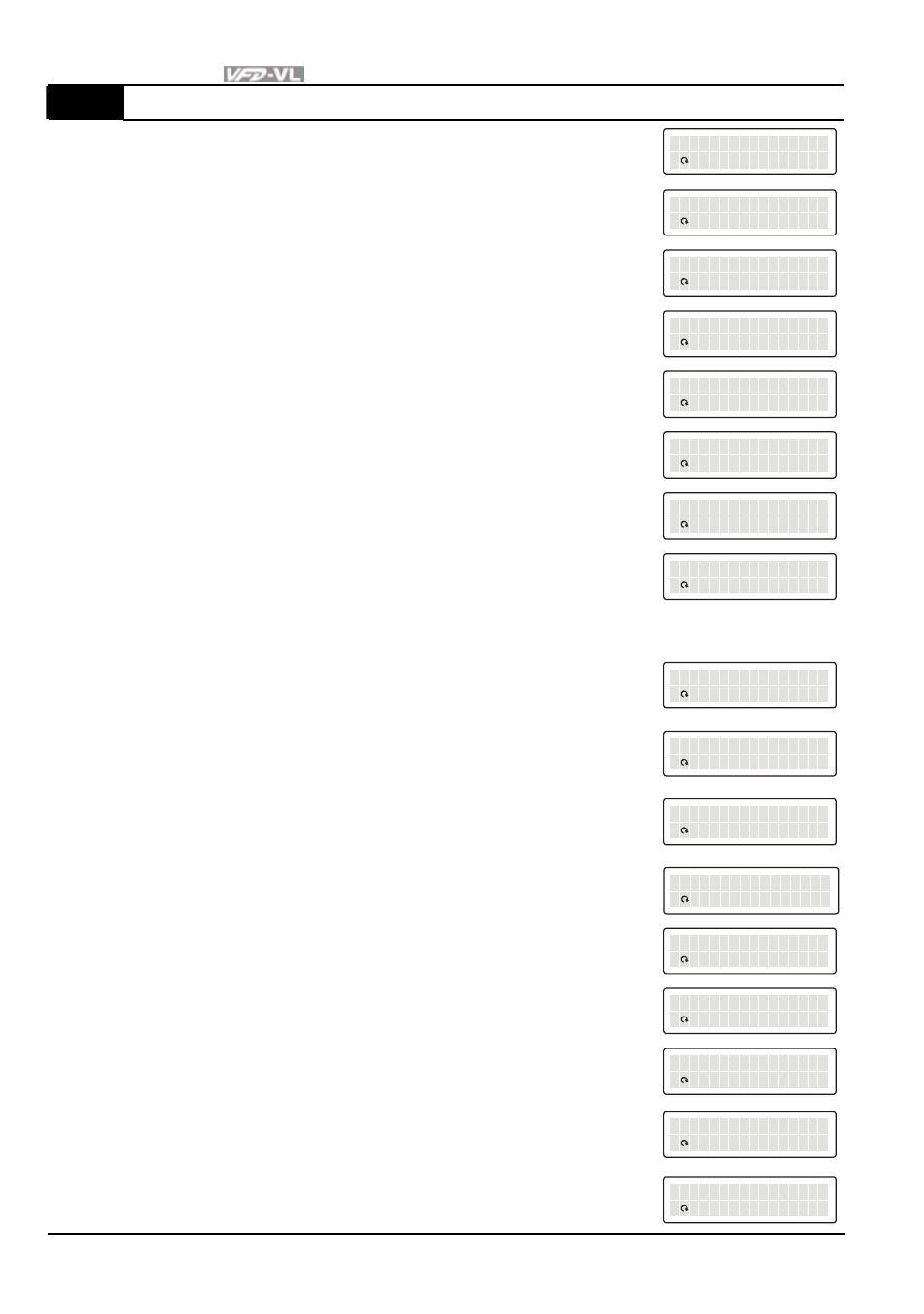
00-04
Content of Multi-Function Display
2 Display actual output frequency (H)
A
U:
u
c t
E
al
e
Fr q
E
.
E
E
S
E
E
EE
0
EE
0
. 0 H
E
z
E
3
Display the actual DC BUS voltage in VDC of the
AC motor drive
D
U:
B
C
E
E
US
E
EE E
E
EE
E
S
E
E
EE
5
E
2
3
5. V
t
ol
4
Display the output voltage in VAC of terminals U, V,
W to the motor.
O
U:
p
ut
E
ut
l
Vo t
e
ag
E
S
E
E
EE
5
E2
0
0. V
t
ol
5
Display the power factor angle in º of terminals U, V,
W to the motor.
P
U:
e
ow
A
r
E
l
ng e
E
EE
E
S
E
E
EE
5
E2
0
0. d
E
eg
6
Display the output power in kW of terminals U, V
and W to the motor.
O
U:
p
ut
E
ut
w
Po e
E
r
E
E
S
E
E
EE
.
E
0
0
00 K
E
E
W
7
Display the actual motor speed in rpm (enabled
when using with PG card).
M
U:
o
ot
S
r
E
e
pe d
E
EE
E
S
E
E
EE
E
EE
0
EE
R
E
M
P
8
Display the estimated value of torque in kg-m as it
relates to current.
T
U:
q
or
E
ue
E
EE E
E
EE
E
S
E
E
EE
E
EE
0
0. N
M
-
t
9 Display PG position
P
U:
F
G
E
d
ee
c
ba k
E
EE
E
S
E
E
EE
1
EE
7
56
E
E
E
E
10
Reserved
11
Display the signal of AUI1 analog input terminal in
%.
Range 0~10V corresponds to 0~100%. (1.)
A
U:
1
UI
E
EE
E
EE E
E
EE
E
S
E
E
EE
E
EE
3
0.
E
E
E
%
12
Display the signal of ACI analog input terminal in %.
Range 4~20mA/0~10V corresponds to 0~100%. (2.)
A
U:
E
CI
E
EE
E
EE E
E
EE
E
S
E
E
EE
E
EE
0
0.
E
E
E
%
13
Display the signal of AUI2 analog input terminal in
%.
Range -10V~10V corresponds to 0~100%. (3.)
A
U:
2
UI
E
EE
E
EE E
E
EE
E
S
E
E
EE
E
EE
3
0.
E
E
E
%
14
Display the temperature of heat sink (°C)
H
U:
t
ea
i
E
S
E
nk
E
E
EE
E
S
E
E
EE
4
EE
0
0.
E
E
C
E
15
Display the temperature of IGBT in
°C.
I
U:
T
GB
e
E
T
E
mp
E
E
EE
E
S
E
E
EE
4
EE
3
1.
E
E
C
E
16 Display digital input status ON/OFF (i)
D
U:
O
I
E
O
N/
E
FF S
t
t a
E
S
E
E
EE
0
EE
0
00
E
E
E
E
17 Display digital output status ON/OFF (o)
D
U:
O
O
E
O
N/
E
FF S
t
t a
E
S
E
E
EE
0
EE
0
00
E
E
E
E
18
Display
multi-step
speed
M
U:
t
ul
S
i -
e
pe d
E
EE
E
S
E
E
EE
0
EE
0
00
E
E
E
E
19 The corresponding CPU pin status of digital input (i.)
D
U:
P
I
E
E
i n
a
St t
E
us
E
S
E
E
EE
F
EE
F
FF
E
E
E
E