Delta Electronics Elevator Drive VFD-VL User Manual
Page 106
Chapter 4 Parameters|
Revision Nov. 2008, VLE1, SW V1.03 4-51
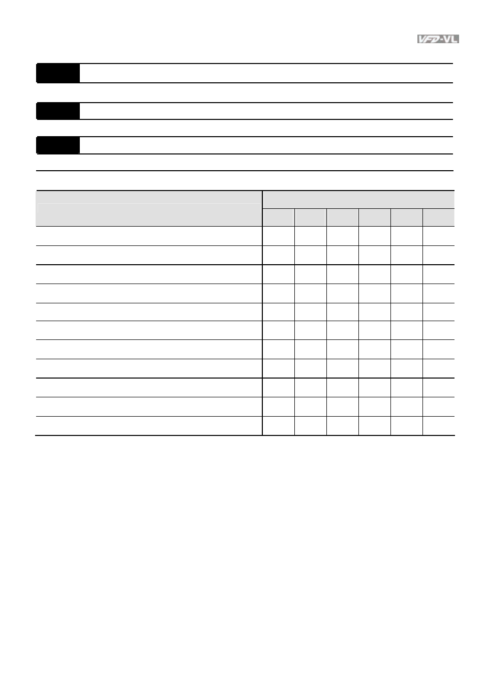
Group 3 Analog Input/Output Parameters
03-00
Analog Input 1 (AUI1)
Factory Setting: 1
03-01
Analog Input 2 (ACI)
Factory Setting: 0
03-02
Analog Input 3 (AUI2)
Factory Setting: 0
Control Mode
Settings
VF
VFPG
SVC
FOCPG TQCPG FOCPM
0: No function
○
○
○
○
○
○
1: Frequency command (torque limit under TQR control mode)
○
○
○
○
○
○
2: Torque command (torque limit under speed mode)
○
3: Torque compensation command
○
○
○
○
○
○
4-5:
Reserved
6: P.T.C. thermistor input value
○
○
○
○
○
○
7: Positive torque limit
○
○
8: Negative torque limit
○
○
9: Regenerative torque limit
○
○
10: Positive/negative torque limit
○
○
11: Preload Input
○
When it is frequency command or TQR speed limit, the corresponding value for 0~±
10V/4~20mA is 0 – max. output frequency(Pr.01-00)
When it is torque command or torque limit, the corresponding value for 0~±10V/4~20mA is 0 –
max. output torque (Pr.07-14).
When it is torque compensation, the corresponding value for 0~±10V/4~20mA is 0 – rated
torque.
- 1x9 Bi-Directional Transceiver Module OPBD-155F2J1R (7 pages)
- Single Mode SFP Transceiver LCP-1250B4MDRx (14 pages)
- LC-1250xxxx Series (10 pages)
- Human Machine Interface DOP-AS Series (329 pages)
- Analog Output Module DVP04DA-S (2 pages)
- DeviceNet Slave Communication Module IFD9502 (2 pages)
- LCP-155B4MSRx (12 pages)
- High-Speed PCI 12-Axis Motion Control Card PCI-DMC-B01 (528 pages)
- Network Device DVP01PU-S (2 pages)
- GBIC-1250D5MR (12 pages)
- SPBD-1250A4Q1RT (10 pages)
- SILM4015 (1 page)
- LCP-8500A4EDR (14 pages)
- 10GBASE-SR SFP+ Optical Transceiver LCP-10G3A4EDR (16 pages)
- LCP-155A4HSRx (11 pages)
- LCP-1250RJ3SR-L (9 pages)
- SILM320L (1 page)
- LCP-1250RJ3SR-S (9 pages)
- SIL530 (1 page)
- Extension Digital I/O Module DOP-EXIO28RAE (1 page)
- DVP Series PLC DVP04TC-H2 (2 pages)
- 1x9 Bi-Directional Transceiver Module OPBD-155F1J1R (7 pages)
- Distribution Box TAP-CN01/02/03 (2 pages)
- LCP-200A4HSR (9 pages)
- Pulse Generation Unit DVP01PU-H2 (2 pages)
- Power Connection Interface VFD-PSD01 (1 page)
- Programmable Logic Controller DVP04DA-H2 (2 pages)
- Single Mode SFP Transceiver LCP-1250B4QDRx (13 pages)
- LCP-155B4JSRx Series (12 pages)
- Series Temperature Controller DTD Series (2 pages)
- Brake Modules BUE Series (2 pages)
- PLC DVP Series DVP-SX (2 pages)
- Digital Keypad / Display ASD-PU-01A (1 page)
- Multimode SFP Transceiver LCP-1250A4FDRx (14 pages)
- HMU1362M (1 page)
- RPA-01 (1 page)
- THMR1395 (1 page)
- SFBD-155F2J1RM (7 pages)
- Program Transfer Module DVP-PCC01 (1 page)
- RTU-DNET (41 pages)
- AC Servo Drive ASDA-AB (37 pages)
- Digital Keypad / Display ASD-PU-01B (1 page)
- HMR1045 (1 page)
- CANopen Communication Module DVPCOPM-SL (2 pages)
- SPBD-1250B4Q1R (10 pages)