3 main circuit, 1 main circuit connection, 3 main circuit -7 – Delta Electronics Elevator Drive VFD-VL User Manual
Page 32: 1 main circuit connection -7, 3 main circuit 2.3.1 main circuit connection
Chapter 2 Installation and Wiring|
Revision Nov. 2008, VLE1, SW V1.03 2-7
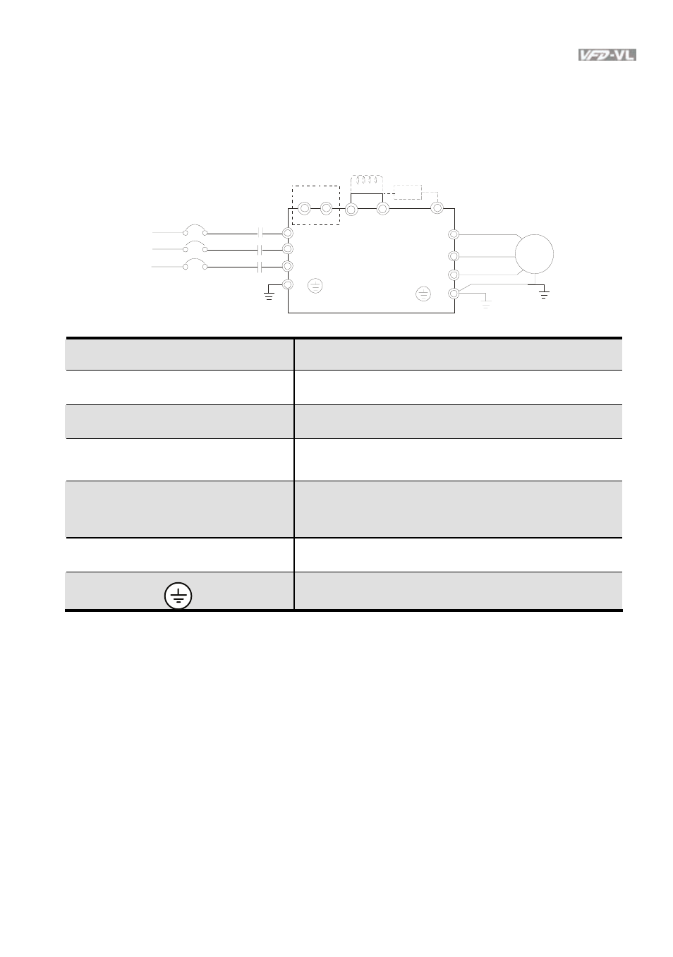
2.3 Main Circuit
2.3.1 Main Circuit Connection
Non-fuse br eak er
( NF B)
Br ak e r es istor
(O pti onal)
Motor
R (L1 )
S(L2 )
T(L 3)
R
S
T
U (T 1)
V(T2 )
W(T 3)
IM
3 ~
MC
E
E
+1 +2/B1
B2
+
-
EPS
*
Terminal Symbol
Explanation of Terminal Function
EPS (+, -)
For emergency power or backup power supply
R/L1, S/L2, T/L3
AC line input terminals
U/T1, V/T2, W/T3
AC drive output terminals for connecting 3-phase
induction motor
+1, +2/B1
Connections for DC Choke (optional). Please remove
jumper when installation. (It is built in DC choke for
models 22kW and above)
+2/B1, B2
Connections for Brake Resistor (optional)
Earth connection, please comply with local regulations.
See also other documents in the category Delta Electronics Hardware:
- 1x9 Bi-Directional Transceiver Module OPBD-155F2J1R (7 pages)
- Single Mode SFP Transceiver LCP-1250B4MDRx (14 pages)
- LC-1250xxxx Series (10 pages)
- Human Machine Interface DOP-AS Series (329 pages)
- Analog Output Module DVP04DA-S (2 pages)
- DeviceNet Slave Communication Module IFD9502 (2 pages)
- LCP-155B4MSRx (12 pages)
- High-Speed PCI 12-Axis Motion Control Card PCI-DMC-B01 (528 pages)
- Network Device DVP01PU-S (2 pages)
- GBIC-1250D5MR (12 pages)
- SPBD-1250A4Q1RT (10 pages)
- SILM4015 (1 page)
- LCP-8500A4EDR (14 pages)
- 10GBASE-SR SFP+ Optical Transceiver LCP-10G3A4EDR (16 pages)
- LCP-155A4HSRx (11 pages)
- LCP-1250RJ3SR-L (9 pages)
- SILM320L (1 page)
- LCP-1250RJ3SR-S (9 pages)
- SIL530 (1 page)
- Extension Digital I/O Module DOP-EXIO28RAE (1 page)
- DVP Series PLC DVP04TC-H2 (2 pages)
- 1x9 Bi-Directional Transceiver Module OPBD-155F1J1R (7 pages)
- Distribution Box TAP-CN01/02/03 (2 pages)
- LCP-200A4HSR (9 pages)
- Pulse Generation Unit DVP01PU-H2 (2 pages)
- Power Connection Interface VFD-PSD01 (1 page)
- Programmable Logic Controller DVP04DA-H2 (2 pages)
- Single Mode SFP Transceiver LCP-1250B4QDRx (13 pages)
- LCP-155B4JSRx Series (12 pages)
- Series Temperature Controller DTD Series (2 pages)
- Brake Modules BUE Series (2 pages)
- PLC DVP Series DVP-SX (2 pages)
- Digital Keypad / Display ASD-PU-01A (1 page)
- Multimode SFP Transceiver LCP-1250A4FDRx (14 pages)
- HMU1362M (1 page)
- RPA-01 (1 page)
- THMR1395 (1 page)
- SFBD-155F2J1RM (7 pages)
- Program Transfer Module DVP-PCC01 (1 page)
- RTU-DNET (41 pages)
- AC Servo Drive ASDA-AB (37 pages)
- Digital Keypad / Display ASD-PU-01B (1 page)
- HMR1045 (1 page)
- CANopen Communication Module DVPCOPM-SL (2 pages)
- SPBD-1250B4Q1R (10 pages)