B.8.4 emvl-pgs01 – Delta Electronics Elevator Drive VFD-VL User Manual
Page 229
Appendix B Accessories|
B-32
Revision Nov. 2008, VLE1, SW V1.03
that B leads A. A-/A is a square wave input. B/O-/B/O and B-/B should be input
synchronously.
A/O-/A/O is the output of frequency divider.
Z/O-/Z/O of the PG card will act by the input signal of Z-/Z and don’t have the function of
frequency divider.
When changing the denominator of the frequency divider or input/output type, it needs to
clear the counter value by clock reset bit (PIN4) before operation. Please set the switch to
1 after reset.
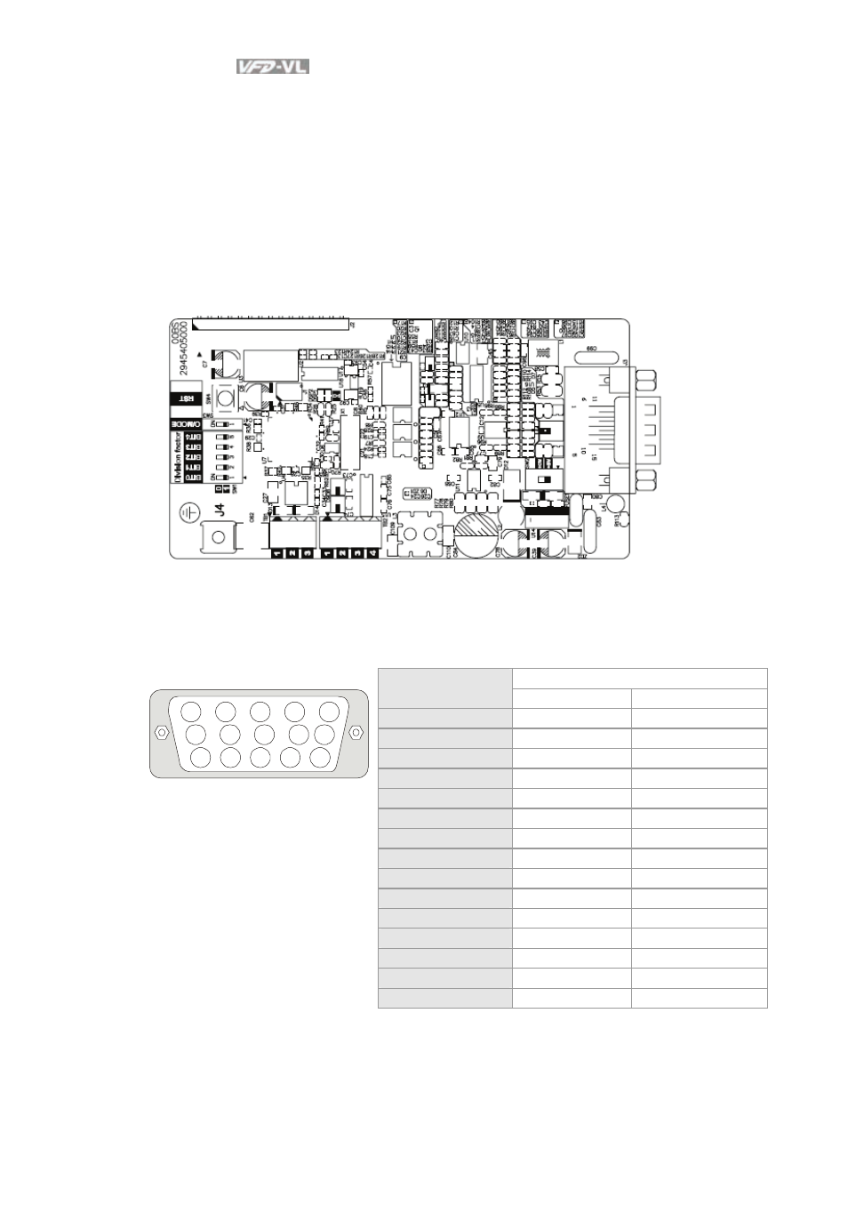
B.8.4 EMVL-PGS01
Applicable encoders for EMVL-PGS01:
EnDat2.1: EQN425, EQN1325, ECN113, ECN413, ECN1113, ECN1313
HIPERFACE: SRS50/60
1. Pin description
Corresponding terminal
VFD-VL Series
Pin No.
EnDat HIPERFACE®
1 B-
REFSIN
2 0V 0V
3 0V 0V
4 0V
0V
5 A+
+COS
6 A-
REFCOS
7 0V 0V
8 B+
+SIN
9 VP VP
10 Data+
Data+
11 Data-
Data-
12 CLOCK+ -
13 CLOCK- -
14 VP VP
VFD-VL Series
5
4
3
2
1
10
9
8
7 6
15 14 13 12 11
15 0V 0V
- 1x9 Bi-Directional Transceiver Module OPBD-155F2J1R (7 pages)
- Single Mode SFP Transceiver LCP-1250B4MDRx (14 pages)
- LC-1250xxxx Series (10 pages)
- Human Machine Interface DOP-AS Series (329 pages)
- Analog Output Module DVP04DA-S (2 pages)
- DeviceNet Slave Communication Module IFD9502 (2 pages)
- LCP-155B4MSRx (12 pages)
- High-Speed PCI 12-Axis Motion Control Card PCI-DMC-B01 (528 pages)
- Network Device DVP01PU-S (2 pages)
- GBIC-1250D5MR (12 pages)
- SPBD-1250A4Q1RT (10 pages)
- SILM4015 (1 page)
- LCP-8500A4EDR (14 pages)
- 10GBASE-SR SFP+ Optical Transceiver LCP-10G3A4EDR (16 pages)
- LCP-155A4HSRx (11 pages)
- LCP-1250RJ3SR-L (9 pages)
- SILM320L (1 page)
- LCP-1250RJ3SR-S (9 pages)
- SIL530 (1 page)
- Extension Digital I/O Module DOP-EXIO28RAE (1 page)
- DVP Series PLC DVP04TC-H2 (2 pages)
- 1x9 Bi-Directional Transceiver Module OPBD-155F1J1R (7 pages)
- Distribution Box TAP-CN01/02/03 (2 pages)
- LCP-200A4HSR (9 pages)
- Pulse Generation Unit DVP01PU-H2 (2 pages)
- Power Connection Interface VFD-PSD01 (1 page)
- Programmable Logic Controller DVP04DA-H2 (2 pages)
- Single Mode SFP Transceiver LCP-1250B4QDRx (13 pages)
- LCP-155B4JSRx Series (12 pages)
- Series Temperature Controller DTD Series (2 pages)
- Brake Modules BUE Series (2 pages)
- PLC DVP Series DVP-SX (2 pages)
- Digital Keypad / Display ASD-PU-01A (1 page)
- Multimode SFP Transceiver LCP-1250A4FDRx (14 pages)
- HMU1362M (1 page)
- RPA-01 (1 page)
- THMR1395 (1 page)
- SFBD-155F2J1RM (7 pages)
- Program Transfer Module DVP-PCC01 (1 page)
- RTU-DNET (41 pages)
- AC Servo Drive ASDA-AB (37 pages)
- Digital Keypad / Display ASD-PU-01B (1 page)
- HMR1045 (1 page)
- CANopen Communication Module DVPCOPM-SL (2 pages)
- SPBD-1250B4Q1R (10 pages)