Delta Electronics Elevator Drive VFD-VL User Manual
Page 102
Chapter 4 Parameters|
Revision Nov. 2008, VLE1, SW V1.03 4-47
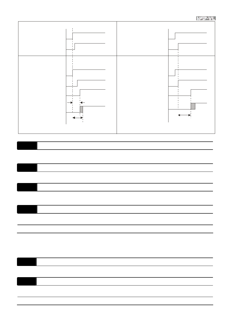
Enable
FW D/REV
Enable
FW D/REV
02-31
Contr oller
Signal output
Driv er
Multifunction
output/input
Multifunction
output=15
Motor
Electr omagnetic
valv e
02-31
no v ol tage output
Contr oller
Signal output
Enable
FW D/REV
Driv er
Multifunction
output/input
Enable
FW D/REV
Multifunction
output=15
Motor
Electr omagnetic
valv e
02-25
Desired Frequency Attained 1
Unit: 0.01
Control
mode
VF VFPG SVC
FOCPG FOCPM
Factory setting: 60.00/50.00
02-26
The Width of the Desired Frequency Attained 1
Unit: 0.01
Control
mode
VF
VFPG
SVC
FOCPG FOCPM
Factory setting: 2.00
02-27
Desired Frequency Attained 2
Unit: 0.01
Control
mode
VF VFPG SVC
FOCPG FOCPM
Factory setting: 60.00/50.00
02-28
The Width of the Desired Frequency Attained 2
Unit: 0.01
Control
mode
VF
VFPG
SVC
FOCPG FOCPM
Factory setting: 2.00
Settings
0.00 ~ 120.00Hz
Once output frequency reaches desired frequency and the corresponding multi-function output
terminal is set to 3 or 4 (Pr.02-11~Pr.02-22), this multi-function output terminal will be ON.
02-29
Brake Release Delay Time when Elevator Starts
Unit:0.001
Control
mode
VF
VFPG
SVC
FOCPG TQCPG FOCPM
Factory setting: 0.250
02-30
Brake Engage Delay Time when Elevator Stops
Unit:0.001
Control
mode
VF
VFPG
SVC
FOCPG TQCPG FOCPM
Factory setting: 0.250
Settings
0.000~65.000 Sec