Group 2 digital input/output parameters – Delta Electronics Elevator Drive VFD-VL User Manual
Page 60
Chapter 4 Parameters|
Revision Nov. 2008, VLE1, SW V1.03 4-5
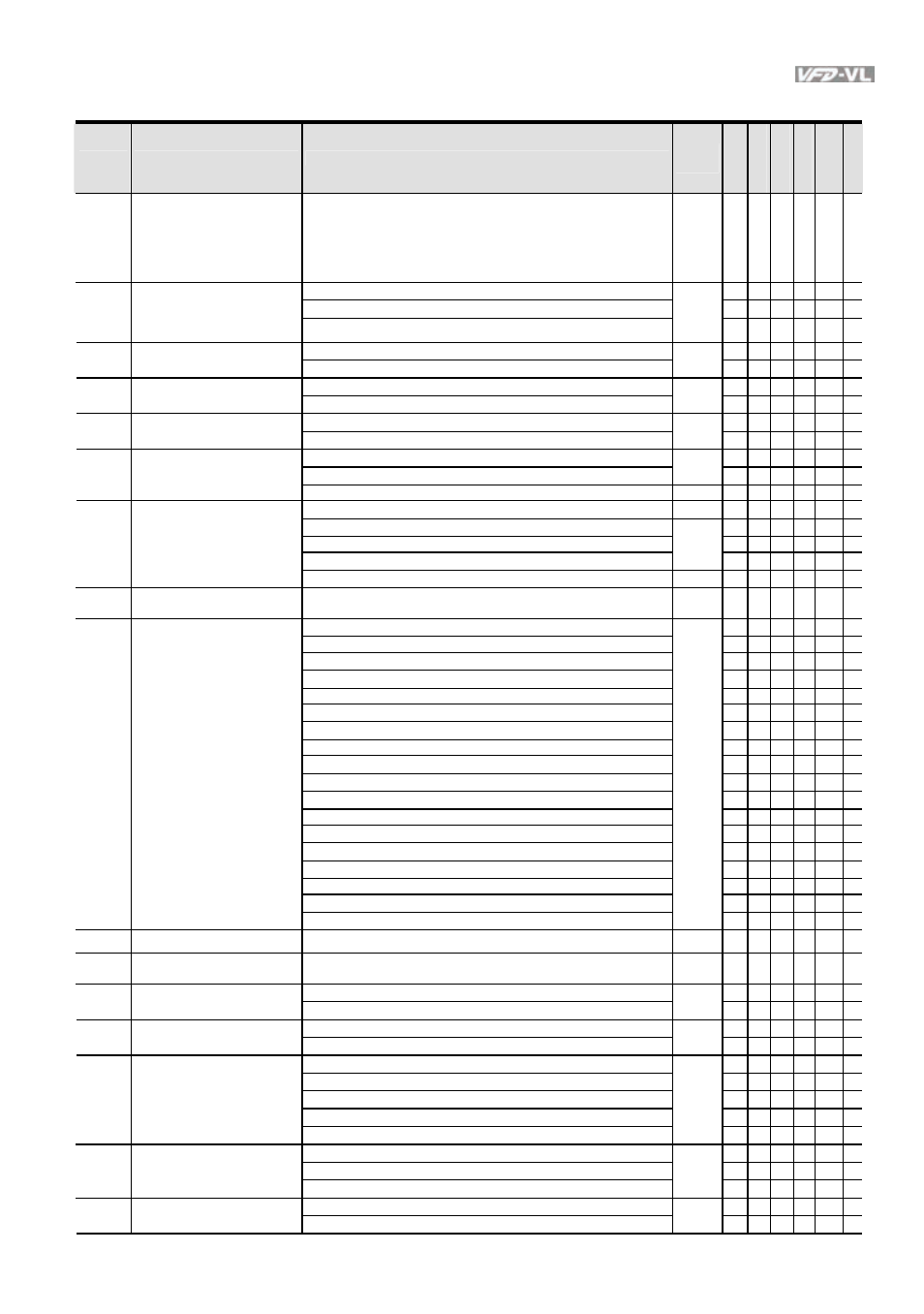
Group 2 Digital Input/Output Parameters
Pr.
Explanation
Settings
Factory
Setting
VF
VF
PG
SVC
FOC
PG
TQC
PG
FOC
PM
02-00 2-wire/3-wire
Operation
Control
0: FWD/STOP, REV/STOP
1: FWD/STOP, REV/STOP (Line Start Lockout)
2: RUN/STOP, REV/FWD
3: RUN/STOP, REV/FWD (Line Start Lockout)
4: 3-wire
5: 3-wire (Line Start Lockout)
0
○ ○ ○ ○ ○ ○
0: no function
○ ○ ○ ○ ○ ○
1: multi-step speed command 1
○ ○ ○ ○
○
02-01 Multi-Function
Input
Command 1 (MI1)
(it is Stop terminal for 3-wire
operation)
2: multi-step speed command 2
1
○ ○ ○ ○
○
3: multi-step speed command 3
○ ○ ○ ○
○
02-02 Multi-Function Input
Command 2 (MI2)
4: multi-step speed command 4
2
○ ○ ○ ○
○
5: Reset
○ ○ ○ ○ ○ ○
02-03 Multi-Function Input
Command 3 (MI3)
6: JOG command
3
○ ○ ○ ○
○
7: acceleration/deceleration speed inhibit
4
○ ○ ○ ○
○
02-04 Multi-Function Input
Command 4 (MI4)
8: the 1st, 2nd
acceleration/deceleration time selection
○ ○ ○ ○
○
9: the 3rd, 4th
acceleration/deceleration time selection
0
○ ○ ○ ○
○
10: EF input (07-28)
○ ○ ○ ○ ○ ○
02-05
Multi-Function Input
Command 5 (MI5)
11: Reserved
12: Stop output
○ ○ ○ ○ ○ ○
13: Disable auto accel./decel. function
○ ○ ○ ○
○
14: Reserved
0
15: operation speed command form AUI1
○ ○ ○ ○
○
02-06
Multi-Function Input
Command 6 (MI6)
16: operation speed command form ACI
○ ○ ○ ○
○
02-07 Multi-Function
Input
Command 7 (MI7)
17: operation speed command form AUI2
0
○ ○ ○ ○
○
02-08
18: Emergency Stop (07-28)
0
○ ○ ○ ○ ○ ○
19-23:
Reserved
Multi-Function Input
Command 8 (MI8) (specific
terminal for Enable)
24: FWD JOG command
○ ○ ○ ○
○
25: REV JOG command
○ ○ ○ ○
○
26:
Reserved
27: ASR1/ASR2 selection
○ ○ ○ ○
○
28: Emergency stop (EF1) (Motor coasts to stop)
○ ○ ○ ○ ○ ○
29-30:
Reserved
31: High torque bias (by Pr.07-21)
○ ○ ○ ○ ○ ○
32: Middle torque bias (by Pr.07-22)
○ ○ ○ ○ ○ ○
33: Low torque bias (by Pr.07-23)
○ ○ ○ ○ ○ ○
34-37:
Reserved
38: Disable write EEPROM function
○ ○ ○ ○ ○ ○
39: Torque command direction
○
40: Enable drive function
○ ○ ○ ○ ○ ○
41:
Reserved
42: Mechanical brake
○ ○ ○ ○ ○ ○
43:
EPS
function
○ ○ ○ ○ ○ ○
02-09
Digital Input Response Time 0.001~ 30.000 sec
0.005
○ ○ ○ ○ ○ ○
02-10
Digital Input Operation
Direction
0 ~ 65535
0
○ ○ ○ ○ ○ ○
0: No function
11
○ ○ ○ ○ ○ ○
02-11
Multi-function Output 1 RA,
RB, RC(Relay1)
1: Operation indication
○ ○ ○ ○ ○ ○
2: Operation speed attained
1
○ ○ ○ ○ ○ ○
02-12
Multi-function Output 2
MRA, MRC (Relay2)
3: Desired frequency attained 1 (Pr.02-25)
○ ○ ○ ○
○
4: Desired frequency attained 2 (Pr.02-27)
0
○ ○ ○ ○
○
02-13
5: Zero speed (frequency command)
○ ○ ○ ○
○
Multi-function Output 3
(MO1)
6: Zero speed with stop (frequency command)
○ ○ ○ ○
○
7: Over torque (OT1) (Pr.06-05~06-07)
○ ○ ○ ○ ○ ○
8: Over torque (OT2) (Pr.06-08~06-10)
○ ○ ○ ○ ○ ○
9: Drive ready
0
○ ○ ○ ○ ○ ○
02-14
Multi-function Output 4
(MO2)
10: User-defined Low-voltage Detection (LV)
○ ○ ○ ○ ○ ○
11:
Malfunction
indication
○ ○ ○ ○ ○ ○
12: Mechanical brake release (Pr.02-29, Pr.02-30)
○ ○ ○ ○ ○ ○
02-15
Multi-function Output 5
(MO3)
13: Overheat (Pr.06-14)
0
○ ○ ○ ○ ○ ○