Delta Electronics Elevator Drive VFD-VL User Manual
Page 27
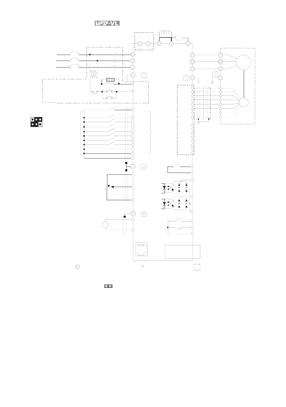
Chapter 2 Installation and Wiring|
2-2
Revision Nov. 2008, VLE1, SW V1.03
FW D
REV
MI1
MI2
MI3
MI4
MI6
MI5
MI7
U(T 1)
V(T 2)
W( T3)
IM/PM
1 2 3 4 5 6
*RS-485
To communicate to PC, it needs
to use converter (VFD-USB01 or
IFD8500).
R(L1)
S(L2)
T(L3)
NFB
R
S
T
RB
RC
+1 +2/B1
B2
RA
RB
RC
E
E
MC
SA
OFF
ON
MC
MC
E
1: +EV
2: GND
3: SG-
4: SG+
5: NC
6: NC
+
-
EPS
MI8
(*1)
COM
+10V
AUI1/AUI2
*
ACI
ACM
E
4~20mA
A
P
G
C
a
rd
(
opt
io
na
l)
Line drive r
PG
U
V
W
*
F us e/NFB(No F use B reaker)
Br ak e res istor
(optional)
Motor
Br ak e res istor/Unit( optional)
Refer to Appendi x B for the us e of
special brake resi stor /uni t
Recommended Circuit
when power s uppl y
is turned O FF by a
fault output
Fact ory set ting :
SINK Mod e
multif unction
te rmin als
increment al encode r
F ac tor y
setting
For wa r d/S TO P
Rever se/STO P
Mu lti-st ep 1
Multi-st ep 2
Mul ti-st ep 3
Multi -st ep 4
No fu nctio n
(*1)
Digit al Signa l Common
No functi on
No functi on
No fu nction
Please refer to t he
fo llo win g figu re f or wiring
o f S INK mo de an d SOURCE
mod e.
Po wer su pp ly
+1 0V 20mA
-10V
Powe r suppl y
- 10 V 2 0mA
Ma st er
Fr eque ncy
- 10 to 10 V
Ma in ci rcuit ( pow er ) ter minal s
Contr ol cir cu it term inals
S hie lded lead s & C abl e
Mu lti-functi on co nt ac t
o utput 1 ( Rel ay)
2 40VAC 3A
1 20VAC 3A
2 4VD C 3A
factor y setting :
fault ind ic at io n
MO1
MO2
MCM
MRA
MRC
Multi-fu nction cont ac t out pu t 2 ( Re lay )
24 0VAC 3 A
12 0VAC 3 A
24 VD C 3A
facto r y se ttin g:
indicates th at it is r unni ng
Multi-fu nction cont ac t out pu t 3
( ph oto coup le r )
48 VD C 50mA
Multi-fu nctio n cont ac t out pu t 4
( photocoup le r )
Mul ti-fu nctio n
Ph ot oc oup ler O utput
*
*
Terminal EP S is eme rg ency power inp ut t erminal, refer to t he following f igure f or de tails.
For P G card, refe r to Ap pendix B for deta ils.
PG Card (o ption al)
EMV L-PGABL
EMV L-PGABO
EMV L-PGH01
(*1 ) When JP1
o n the co ntrol board is in serted, MI8 is disabled.
EMVL -I OD01
e xte nsion c ar d
( opti onal)