Delta Electronics Elevator Drive VFD-VL User Manual
Page 124
Chapter 4 Parameters|
Revision Nov. 2008, VLE1, SW V1.03 4-69
59
PU time-out (cP10)
60
Brake chopper error (bF)
61-62
Reserved
63
Safety loop error (Sry)
64
Mechanical brake error (MBF)
65
PGF5 hardware error
It will record when the fault occurs and force stopping. For the Lv, it will record when it is
operation, or it will warn without record.
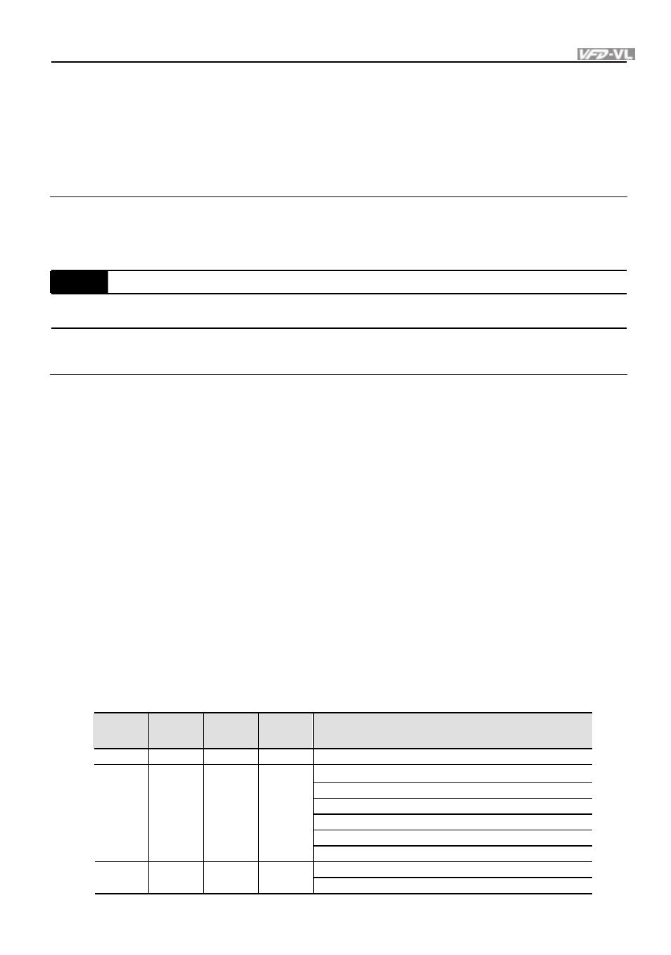
06-30
Setting Method of Fault Output
Control
mode
VF
VFPG
SVC
FOCPG TQCPG FOCPM
Factory setting: 0
Settings
0
By settings of Pr.06-22~06-25
1
By the binary setting
It is used with the settings 35~38 of Pr.02-11~02-22 (Multi-function Output). The fault output
selection 1~4 corresponds to Bit 0~3.
This parameter provides two setting methods for the fault output: setting 0: it is set by the
settings of Pr.06-22~Pr.06-25; setting 1: it is set by the binary setting and please refer to the
following example for details.
Example:
Assume that
Pr.02-15 (Multi-function Output 5 (MO3)) is set to 35 Fault output option 1 (Pr.06-22).
Pr.02-17 (Multi-function Output 7 (MO5)) is set to 36 Fault output option 2 (Pr.06-23).
Pr.02-19 (Multi-function Output 9 (MO7)) is set to 37 Fault output option 3 (Pr.06-24).
Pr.02-21 (Multi-function Output 11 (MO9)) is set to 38 Fault output option 4 (Pr.06-25).
Assume that external faults output with the following signal: MO3=1, MO5=1, MO7=0 and
MO9=1. The corresponding Bit 3~0 is 1011.
Bit 3
Bit 2
Bit 1
Bit 0
Fault code
- - - -
0: No fault
1: Over-current during acceleration (ocA)
2: Over-current during deceleration (ocd)
3: Over-current during constant speed (ocn)
4: Ground fault (GFF)
5: IGBT short-circuit (occ)
0 0 0 1
6: Over-curent at stop (ocS)
7: Over-voltage during acceleration (ovA)
0 0 1 0
8: Over-voltage during deceleration (ovd)