4 maximum battery standby load, 7 installation tasks overview, Installation tasks overview – SilentKnight 5820XL User Manual
Page 31: Warning
LS10061-001SK-E
Before You Begin Installation
3-12
3.6.4
Maximum Battery Standby Load
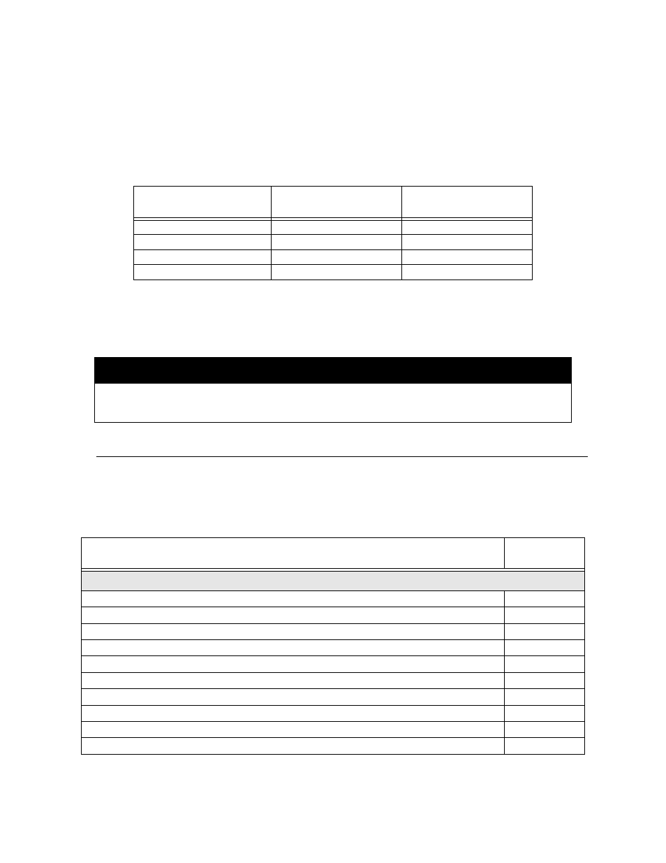
Table 3-4 shows the maximum battery standby load for the 5820XL/5820XL-EVS based on 24 and 60 hours of
standby. The standby load calculations of line D in the Current Draw Calculation Worksheet (Table 3-2 for SK
devices and Table 3-3 SD devices), must be less than the number shown in Table 3-4 for the battery size used and
standby hours required.
*
Required for NFPA 72 Auxiliary Protected Fire Alarm systems for Fire Alarm Service (City Box) and Remote
Station Protected Fire Alarm systems (Polarity Reversal) and Digital Alarm Communicator/Transmitter
(DACT)
*
33AH max battery size for FM (factory mutual) installations.
3.7
Installation Tasks Overview
This section provides a chart listing tasks that need to be performed when installing the 5820XL/5820XL-EVS
system. The chart is intended to be a handy way for you to make sure you have completed all necessary tasks.
Unless noted, these tasks do not have to be performed in the order they are listed here.
Important: Connect and address SLC devices before running JumpStart AutoProgramming.
Table 3-4: Maximum Battery Standby Load
Rechargeable Battery Size
Max. Load for 24 hrs.
Standby, 5 mins. Alarm
*Max. Load for 60 hrs.
Standby, 5 mins. Alarm
7 AH
270 mA
105 mA
12 AH
475 mA
190 mA
18 AH
685 mA
270 mA
35 AH
1.3 A
540 mA
Warning!
Silent Knight does not support the use of batteries smaller than those listed in Table 3-4. If you use a battery too small for
the installation, the system could overload the battery resulting in the installation having less than the required 24 hours
standby power. Use Table 3-4 to calculate the correct battery amperes/hour rating needed for your installation.
Task
See Sec.
(for more info.)
Main Panel Hardware Installation
Mount the control panel cabinet.
Connect AC.
Install 5815XL SLC expander modules. Required if more than 127 SLC devices are used.
Install 5860 Remote Fire Alarm Annunciator modules.
Install 5865 or LED Annunciator modules.
Install 5880 LED I/O modules.
Install notification appliances.
Install auxiliary power devices.
Install the 5824 Serial/Parallel Printer Interface modules.
Connect batteries (typically last step).