What are ladder logic programs – Rockwell Automation 2100-GK61 DeviceNet to SCANport User Manual
Page 77
Publication 2100-UM001B-EN-P – January 2001
Ladder Logic Programming—Including Reading Inputs
5-3
What are Ladder Logic
Programs?
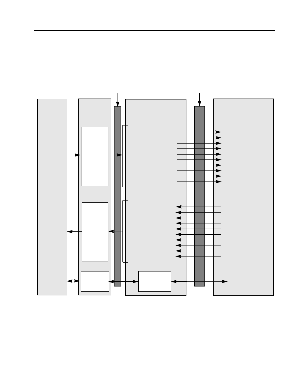
A PLC, SLC, or ControlLogix ladder logic program lets you control
the drive and the messaging from the processor to the drive. Figure
5.1 shows how the I/O image table for a DeviceNet scanner relates to
the 1336 PLUS drive when a DeviceNet to SCANport
Communication Module with Digital Inputs is used.
Figure 5.1
I/O Image Table
Important: Datalinks are optionally enabled in the adapter and configured in the product. Refer to
Chapter 3, Configuring the DeviceNet to SCANport Communication Module with Digital Inputs, and
your product’s user manual for more information.
2100-GK61
Enhanced DeviceNet
Word 0 Logic Command
Word 1 Reference
Word 2 Datalink A1
Word 3 Datalink A2
Word 4 Datalink B1
Word 5 Datalink B2
Word 6 Datalink C1
Word 7 Datalink C2
Word 8 Datalink D1
Word 9 Datalink D2
Logic Status
Feedback
Data Out A1
Data Out A2
Data Out B1
Data Out B2
Data Out C1
Data Out C2
Data Out D1
Data Out D2
1336 PLUS Drive
PLC,
SLC,
PC
SCANport
Output
Mapping
(Write)
Message
Handler
Scanner
Input
Mapping
(Read)
Logic Command
Block
Reference
Data In A1
Data In A2
Data In B1
Data In B2
Data In C1
Data In C2
Data In D1
Word 0 Logic Status
Word 1 Feedback
Word 2 Datalink A1
Word 3 Datalink A2
Word 4 Datalink B1
Word 5 Datalink B2
Word 6 Datalink C1
Word 7 Datalink C2
Word 8 Datalink D1
Word 9 Datalink D2
Message
Buffers
Message Handler
DeviceNet