Rockwell Automation 2100-GK61 DeviceNet to SCANport User Manual
Page 138
Publication 2100-UM001B-EN-P – January 2001
B-12
DeviceNet to SCANport Communication Module with Digital Inputs Parameters
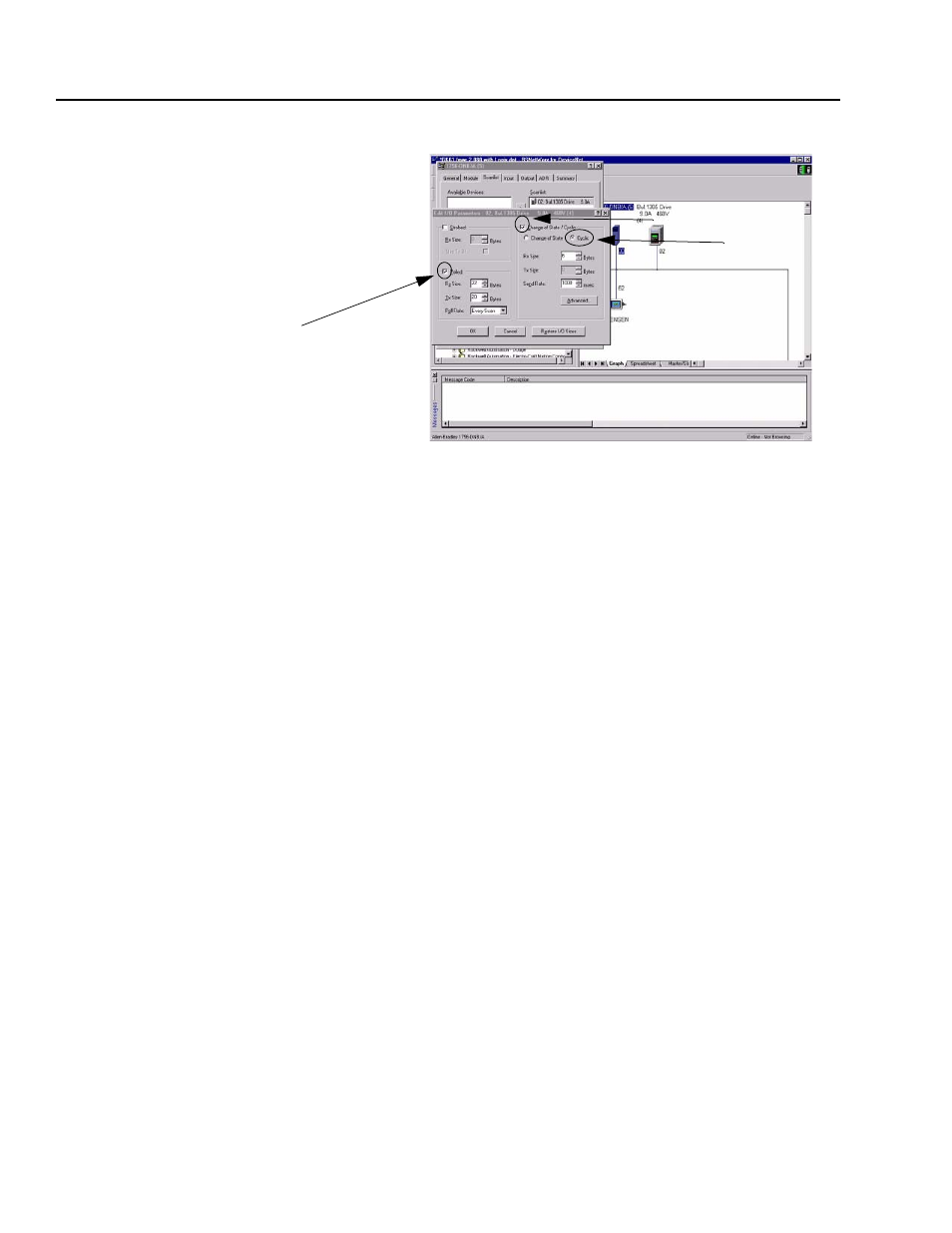
1. In the Polled section, click on the box next to Polled. A “✔”
appears.
2. In the Rx field, enter the size for the I/O input. Enter 4 for each
datalink enabled and 6 if Com/Ref is enabled. For example, if
Cmd/Ref and all 4 datalinks are enabled, you would enter 22.
3. In the Tx field, enter the size of the I/O output. Enter 4 for each
datalink enabled and 4 if Com/Ref is enabled. For example, if
Cmd/Ref and all 4 datalinks are enabled, you would enter 20.
4. In the Poll Rate field, select the appropriate rate.
5. In the Change of State/Cyclic section, click the box next to
Change of State/Cyclic. A “✔” appears.
6. Click Cyclic.
7. In the Rx field, enter 6 for the size of the I/O input.
8. In the Send Rate field, enter the time for the message interval.
9. Click OK.
Using Peer-to-Peer
Communications
To have your adapter receive data from or transmit data to another
2100-GK61, 1203-GU6, or 1336-GM6 on the DeviceNet network,
you must configure it for peer-to-peer communications. Peer-to-peer
communications are best used in the following instances:
•
A PLC sends data to a drive. That drive re-transmits the data to
other drives on the network.
•
A drive is configured on a network. It sends data to other drives
on the network.
Important: After setting up peer-to-peer communications, you must
make sure the configuration that you set up works as you intend it to
work.
Step #5
Step #6
Step #1
Figure B.7
Edit Device I/O Parameters Dialog Box for Polling and Cyclic