Figure b.1 module i/o configuration – Rockwell Automation 2100-GK61 DeviceNet to SCANport User Manual
Page 130
Publication 2100-UM001B-EN-P – January 2001
B-4
DeviceNet to SCANport Communication Module with Digital Inputs Parameters
SCANport devices that support this function have a group of
parameters for datalink configuration. These parameters are Data In
A1 – D2 and Data Out A1 – D2.
If you intend to use command I/O and/or datalinks, you must do the
following:
1. Access the adapter’s parameters using DeviceNet network (refer
to Chapter 3, Configuring the DeviceNet to SCANport
Communication Module with Digital Inputs).
2. Enable the Cmd/Stat Config (4) parameter and/or desired
DataLink (5 – 8) parameters within the DeviceNet to SCANport
Communication Module with Digital Inputs.
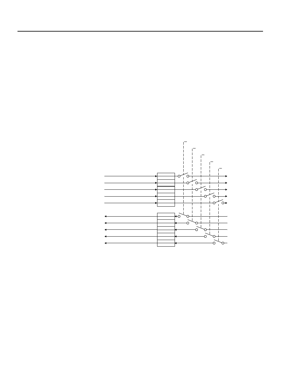
Figure B.1
Module I/O Configuration
3. Configure or link the Data In A1– D2 and Data Out A1 – D2
parameters in the SCANport product. Refer to the documentation
for your SCANport product.
4. Configure the M-S Input parameter and M-S Output parameter as
desired. Refer to the “M-S Input Parameter Configurations”
section or the “M-S Output Parameter Configurations” section in
this chapter.
5. Reset the adapter by setting the Reset Adapter (22) parameter to
Enable.
Reference
Logic Command
DL A2 Inp
DL A1 Inp
DL B2 Inp
DL B1 Inp
DL C2 Inp
DL C1 Inp
DL D2 Inp
DL D1 Inp
Feedback
Logic Status
DL A2 Out
DL A1 Out
DL B2 Out
DL B1 Out
DL C2 Out
DL C1 Out
DL D2 Out
DL D1 Out
Module Input
Module Output
Cmd/Stat Config
Datalink A Confi
Datalink B Confi
Datalink C Confi
Datalink D Confi
Data to the
SCANport
Device
Data from the
SCANport
Device
Data from
DeviceNet
Data to
DeviceNet
g
g
g
g