Rockwell Automation 2100-GK61 DeviceNet to SCANport User Manual
Page 62
Publication 2100-UM001B-EN-P – January 2001
4-26
Configuring a Scanner to Communicate with the Adapter
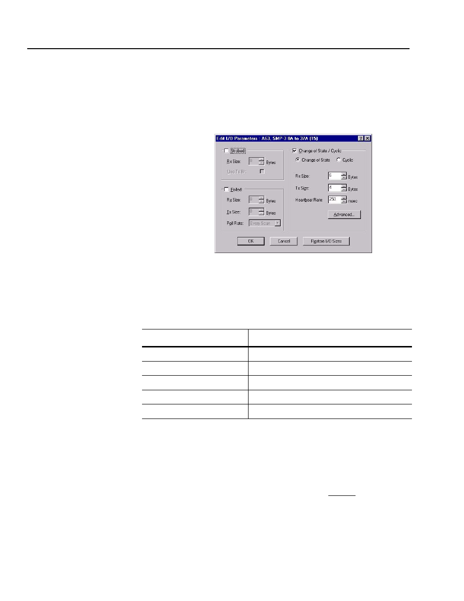
7. Modify each device’s I/O parameters if needed. Select the device
and click on the Edit I/O Parameters button. The I/O Parameters
dialog screen appears.
Figure 4.35
I/O Configuration Edit Screen
8. Make the changes as necessary. You must configure your PLC
based on how your adapter’s parameters are configured and how
you want your module to send and receive data from the network.
Refer to the following table.
9. Click OK to return to the Scanlist screen.
10. Click on the Apply button. A dialog box appears asking if you
wish to download the changes to the device. Click on Yes.
Important: If the processor is not in Program mode, a dialog box
will appear stating which mode the processor is in. Clicking on the
OK button returns you to the Scanlist screen without downloading
any information to the processor. You must now place the process in
program mode and repeat the apply function.
If Using:
Refer To:
Polled
Polled Allocation on page B-5.
COS (Change of State)
COS (Change of State) Allocation on page B-7.
Cyclic
Cyclic Allocation on page B-8.
Polled and COS
Polled and COS Allocation on page B-10.
Polled and Cyclic
Polled and Cyclic Allocation on page B-11.