Enabling the adapter to receive peer i/o, Figure b.7 receiving i/o from a peer device – Rockwell Automation 2100-GK61 DeviceNet to SCANport User Manual
Page 139
Publication 2100-UM001B-EN-P – January 2001
DeviceNet to SCANport Communication Module with Digital Inputs Parameters
B-13
To enable peer-to-peer communications, you must enable one adapter
to transmit peer I/O and one or more adapters to receive peer I/O.
Enabling the Adapter to Receive Peer I/O
To have your DeviceNet to SCANport Communication Module with
Digital Inputs receive input data from another DeviceNet to
SCANport Communication Module with Digital Inputs on the
network, you must configure it for peer-to-peer communications.
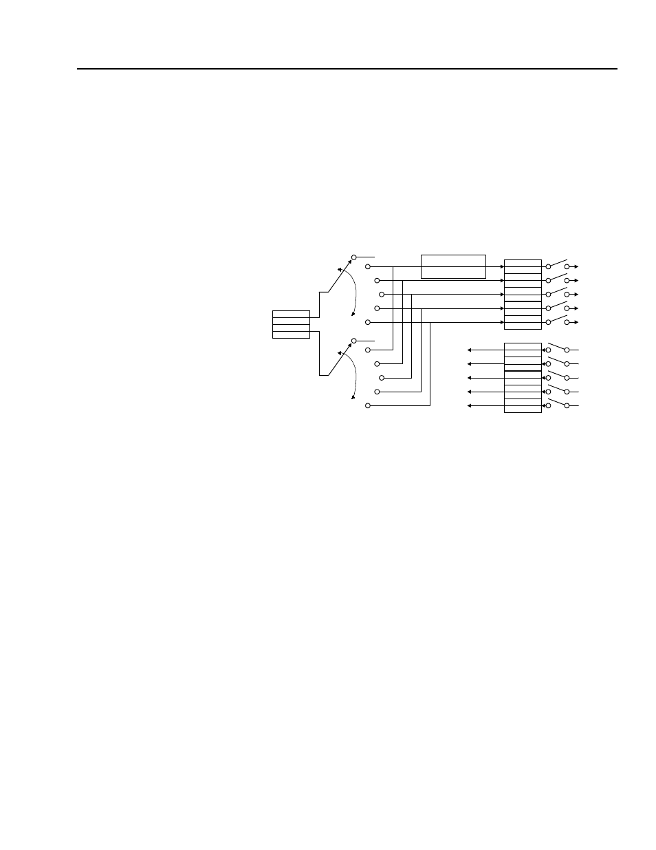
Figure B.7
Receiving I/O from a Peer Device
In Peer-to-Peer communications, you can receive two or four I/O
words from another adapter. Follow these directions:
1. Enable the desired I/O and datalinks within the adapter and
SCANport product. Refer to the “Using Datalinks and Command
I/O” section in this chapter.
2. Ensure the Peer Inp Enable (36) parameter is Off.
3. Set the Peer Node to Inp (34) parameter to the number of the node
from which you want to receive data.
Reference
Logic Command
DL A2 Inp
DL A1 Inp
DL B2 Inp
DL B1 Inp
DL C2 Inp
DL C1 Inp
DL D2 Inp
DL D1 Inp
Feedback
Logic Status
DL A2 Out
DL A1 Out
DL B2 Out
DL B1 Out
DL C2 Out
DL C1 Out
DL D2 Out
DL D1 Out
Module Input
Module Output
Data to the
SCANport
Device
Data from the
SCANport
Device
Peer Input
Data from
DeviceNet
Peer A Word 2
Peer A Word 1
Peer B Word 2
Peer B Word 1
Peer A Input
Peer B Input
Peer Ref Adjust
Peer Cmd Mask