Rockwell Automation 2100-GK61 DeviceNet to SCANport User Manual
Page 59
Publication 2100-UM001B-EN-P – January 2001
Configuring a Scanner to Communicate with the Adapter
4-23
Your device is now configured on the DeviceNet network. The
network LED on the module is solid green. If it is not, refer to
Chapter 7, Troubleshooting, for more information.
Refer to Chapter 5, Ladder Logic Programming—Including Reading
Inputs, for information on creating a PLC Ladder Logic Program.
Configuring an SLC Scanner
(1747-SDN) to Communicate
with the Adapter
The following instructions describe how to configure an SLC scanner
on a DeviceNet network.
For the SLC to recognize your device, you must do the following:
•
Configure the SLC Scanner.
•
Map your adapter to the SLC (1747-SDN).
Configuring an SLC Scanner
To configure the scanner, you verify its properties, add devices on the
network to its scan list, and determine how the scanner will
communicate (e.g., polling) with each device. Follow these
directions:
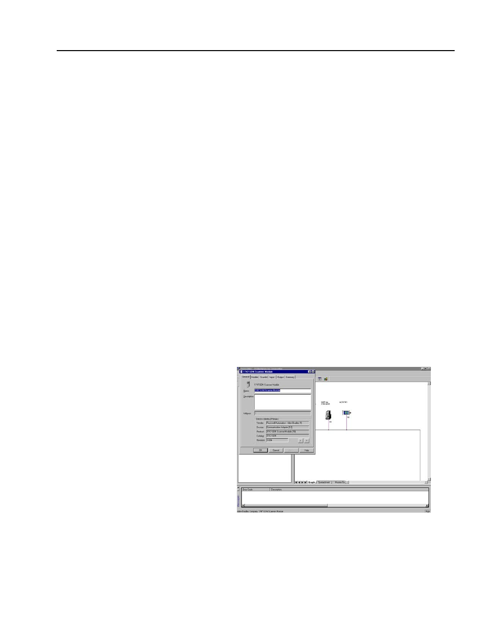
1. In the Online screen, double-click on the scanner icon. The
1747-SDN Scanner Module properties and configuration screen
appears.
Figure 4.31
1747-SDN Configuration Dialog Box
The dialog box contains six data tabs which are used to configure
various portions of the scanner. The General tab allows the user to
edit the name and descriptions of the scanner. The Module tab allows
the user to configure the scanner setup properties. The Scanlist tab